
Econoline E350 1 Ton V8-5.4L Prop SOHC VIN Z (1998)
1.
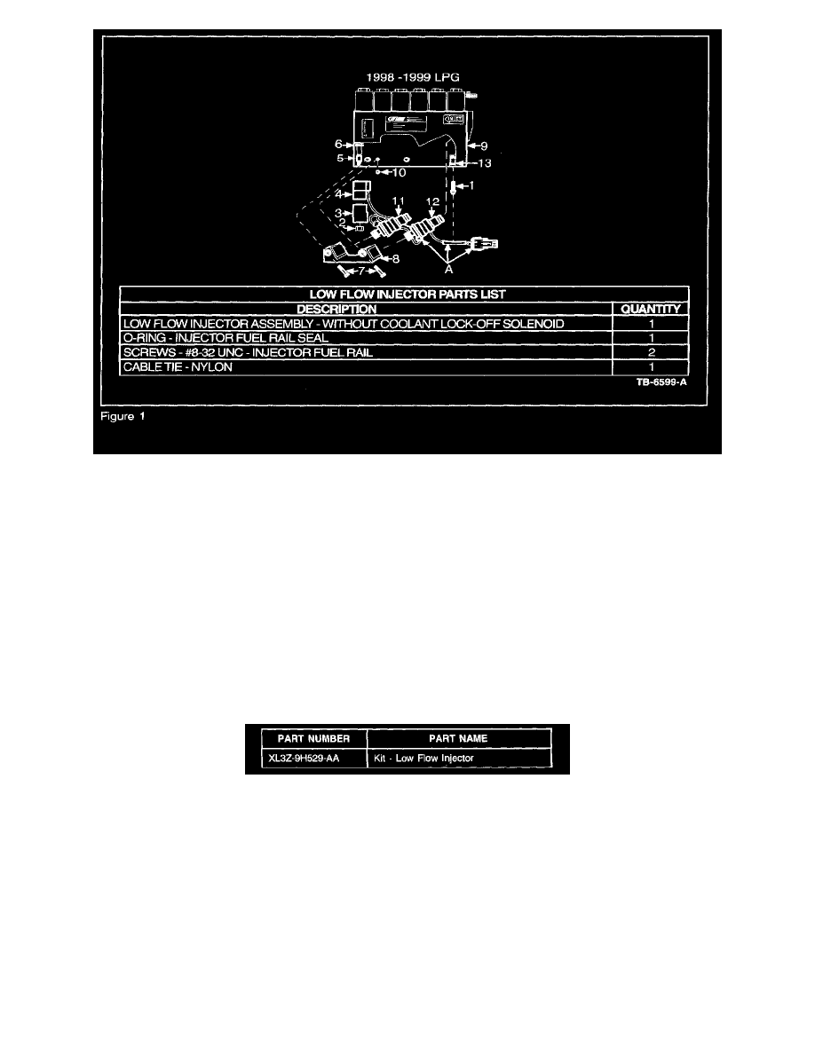
Carefully cut cable tie (1) securing the Low Flow Injector Assembly (A) harness and discard cable tie (Figure 1).
2.
Remove nut (2) and solenoid casing (3) and set aside (Figure 1).
3.
Remove Coolant Lock-off Solenoid (4) from core tube (5) (Figure 1).
NOTE
LEAVE THE RUBBER SPACER (6) IN PLACE ON CORE TUBE (5) AFTER REMOVING COOLANT LOCK-OFF SOLENOID (4) (FIGURE
1).
4.
Remove the two mounting screws (7) securing the Injector Fuel Rail (8) to the Compuvalve (9) and discard screws (Figure 1)
5.
Remove the Low Flow Injector Assembly (A) and Injector Fuel Rail (8) from Compuvalve (9). Discard Low Flow Injector Assembly (A) and set
aside the Injector Fuel Rail (8) (Figure 1).
6.
Remove 0-ring (10) from Compuvalve (9) and discard 0-ring (Figure 1).
NOTE
IF THE COMPUVALVE IS LEFT UNINSTALLED FOR AN EXTENDED PERIOD OF TIME, USE A CLEAN LINT-FREE CLOTH TO
COVER ALL EXPOSED OPENINGS TO AVOID CONTAMINATION.
INSTALLATION OF LOW FLOW INJECTOR ASSEMBLY
Assembly Preparation
1.
Ensure all mating surfaces between Compuvalve (9), Injector Fuel Rail (8) and Low Flow Injectors (11) & (12) are clean (Figure 1).
NOTE
TO CLEAN, GENTLY WIPE SURFACES USING A CLEAN LINT-FREE CLOTH.
2.
Ensure there is lubricant on the inlet and outlet 0-rings of the new Low Flow Injectors (11) & (12) and to 0-ring (11) (Figure 1).