
Econoline E350 1 Ton V8-5.4L Prop SOHC VIN Z (1998)
1.
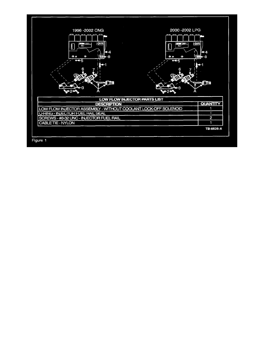
Carefully cut cable tie (1) securing the Low Flow Injector Assembly (A) harness and discard cable tie (Figure 1).
2.
Remove the two mounting screws (2) securing the Injector Fuel Rail (3) to the Compuvalve (4) and discard screws (Figure 1).
3.
Remove the Low Flow Injector Assembly (A) and Injector Fuel Rail (3) from Compuvalve (4). Discard Low Flow Injector assembly (A) and set
aside the Injector Fuel Rail (3) (Figure 1).
4.
Remove 0-ring (5) from Compuvalve (4) and discard 0-ring (Figure 1).
NOTE
IF THE COMPUVALVE IS LEFT UNINSTALLED FOR AN EXTENDED PERIOD OF TIME, USE A CLEAN LINT-FREE CLOTH TO
COVER ALL EXPOSED OPENINGS TO AVOID CONTAMINATION.
INSTALLATION OF LOW FLOW INJECTOR ASSEMBLY
Assembly Preparation
1.
Ensure all mating surfaces between Compuvalve (4), Injector Fuel Rail (3) and Low Flow Injectors (6) & (7) are clean (Figure 1).
NOTE
TO CLEAN, GENTLY WIPE SURFACES USING A CLEAN LINT-FREE CLOTH.
2.
Ensure that lubricant is on both the inlet and outlet 0-rings of the new Low Flow Injectors (6) & (7) and on 0-ring (5) (Figure 1).
NOTE
IF REQUIRED, APPLY A THIN FILM OF NON-SILICONE BASED LUBRICANT FOR 0-RINGS (E.G. PARKER 0-LUBE).
3.
Before installing the Low Flow Injector Assembly (A), ensure that the orientation of injector # 1 (6) (with shorter wire) and of injector # 2 (7)
(with longer wire) are positioned as shown (Figure 1).
Assembly Installation
NOTE
DURING THE INSTALLATION OF THE LOW FLOW INJECTORS, CARE SHOULD BE TAKEN TO PREVENT ANY DEBRIS FROM
ENTERING THE FUEL FLOW OPENINGS.