
Econoline E350 1 Ton V8-5.4L Prop SOHC VIN Z (1998)
NOTE: The semi-float axle shaft riding bearing design uses a differential pinion shaft lock pin that is assembled using a 12-point socket wrench.
Use a new differential pinion shaft lock pin and assemble finger-tight only. This procedure is necessary to prevent the differential side gears and
the differential pinion gears from rotating in the differential case and dropping out when servicing the rear axle differential carrier.
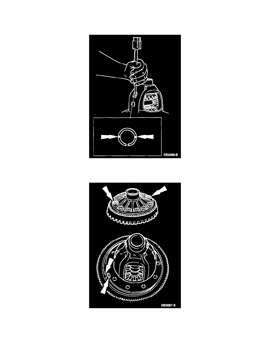
7. For full-floating axle shafts, assemble the differential pinion shaft lock pin. Peen the metal of the differential case over the differential pinion shaft
lock pin in two places, 180 degrees apart, to lock in place. Note the location of the slot in the differential pinion shaft lock pin and peen 90 degrees
away.
8. Align the tab in the anti-lock speed sensor ring with the slot in the differential case. Start the two ring gear bolts through the differential case flange
into the ring gear to make sure the differential case and the ring gear bolt hole align.
NOTE: The tab on the anti-lock speed sensor ring must be aligned with the slot in the differential case.