
Edge AWD V6-3.5L (2009)
Clockspring Assembly / Spiral Cable: Service and Repair
Clockspring
Removal
NOTE: The air bag warning indicator illuminates when the correct Restraints Control Module (RCM) fuse is removed and the ignition is ON.
NOTE: The Supplemental Restraint System (SRS) must be fully operational and free of faults before releasing the vehicle to the customer.
1. Remove the driver air bag module. For additional information, refer to Driver Air Bag Module See: Air Bag/Service and Repair/Driver Air Bag
Module.
2. NOTICE: Vehicles equipped with a steering angle sensor and/or adaptive headlamps, do not allow the clockspring rotor to turn from the
straight-ahead position after the steering wheel is removed. Failure to follow this instruction may result in component damage and/or
system failure.
NOTE: Make sure the road wheels are in the straight-ahead position.
Remove the steering wheel.
3. Tape the clockspring rotor to the steering column shaft to prevent the clockspring rotor from moving out of center.
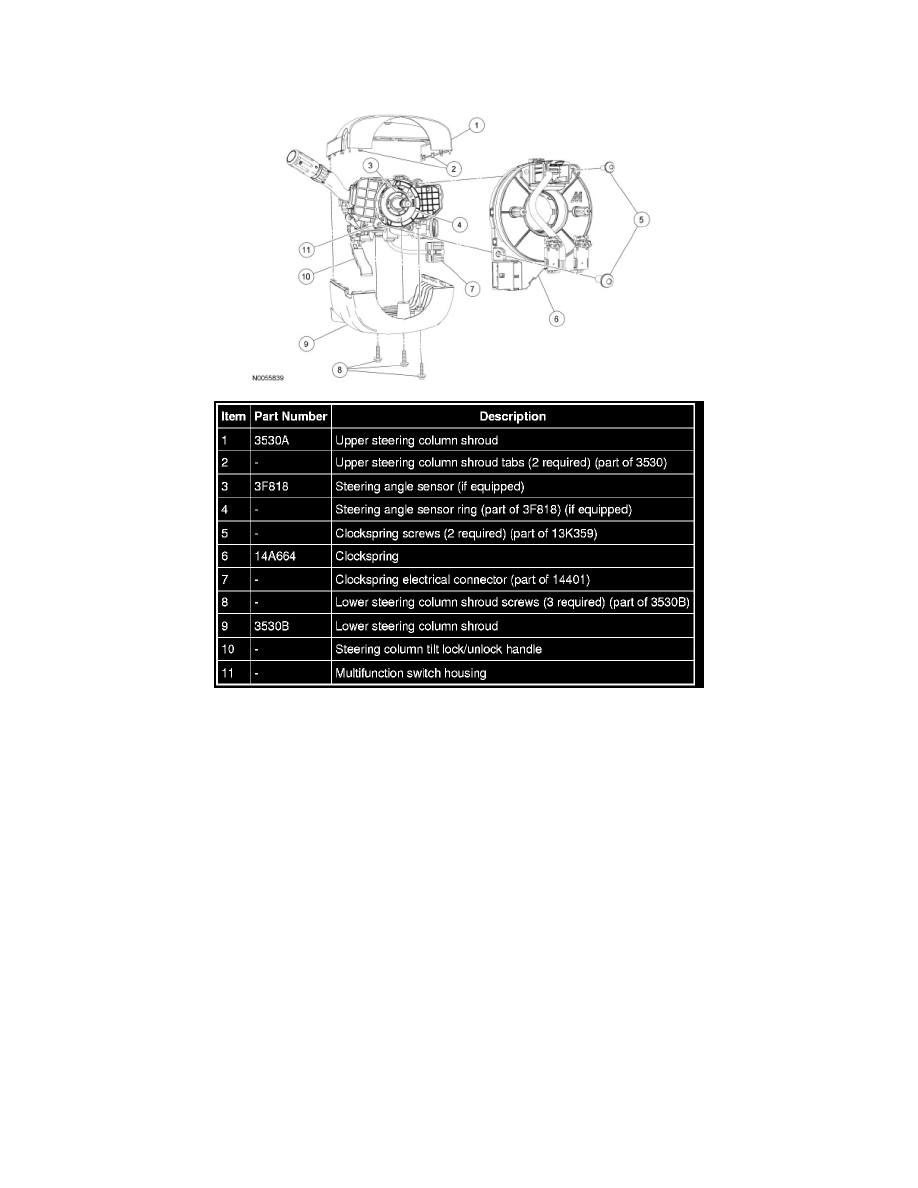
4. Release the 2 tabs and position the upper steering column shroud upward.
5. Remove the 3 screws and the lower steering column shroud.
6. Disconnect the clockspring electrical connector.
7. Remove the tape from the clockspring rotor to the steering column shaft. Do not allow the clockspring rotor to move from center after tape is