
Edge FWD V6-3.5L (2007)
Shift Solenoid: Testing and Inspection
Pinpoint Tests - OSC Equipped Vehicle
Special Tool(s)
Any time an electrical connector or solenoid body is disconnected, inspect the connector for terminal condition, corrosion and contamination. Also
inspect the connector seal for damage. Clean, repair or install new components as required.
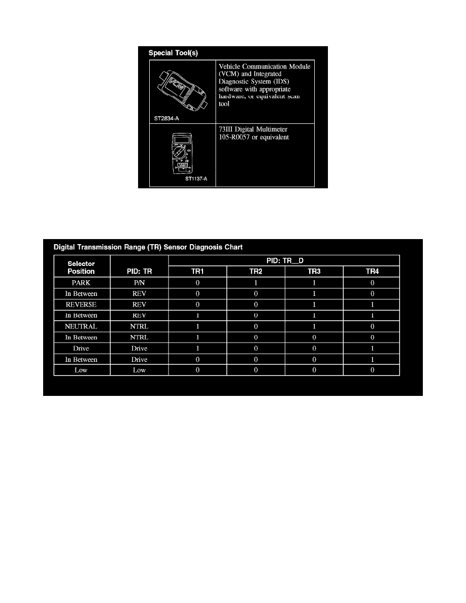
Digital Transmission Range (TR) Sensor Diagnosis Chart
A. "In Between" reading could be caused by a shift cable or digital TR sensor misaligned or a digital TR sensor circuit failure of TR1, TR2, TR3 or
TR4.
B. TRD: 1= Open digital TR switch, 0= Closed digital TR switch.
C. VCM Readings: Taken from PCM signal pins for TR1, TR2, TR3 and TR4 to signal return.
Wiggle Test Information for Open/Shorts
A. Check TR1, TR2, TR3 and TR4 circuits for an intermittent open with the TR sensor positioned so that suspect circuit is in the closed position and
monitor the TR_D with the scan tool.
B. Check TR1, TR2, TR3 and TR4 circuits for an intermittent short with the TR sensor positioned so that suspect circuit is in the open position and
monitor the TRD with the scan tool. To determine the shorted components while observing TRD, unplug the TR and determine if the short goes away. If
the short is still present unplug the transaxle harness and determine if the short goes away. If the short is still present, then the short is in the powertrain
control module (PCM) or vehicle harness. Remove the suspect circuit(s) wire terminal from the PCM connector. If the short is still present, then the
PCM has an internal failure. Otherwise, the failure is in the vehicle harness.
Shift Solenoid Pre-Diagnosis
Use this shift solenoid operation information when carrying out Pinpoint Test A.
Solenoid Operation Chart