
Escape 2WD L4-122 2.0L DOHC VIN B SFI (2001)
Control Assembly: Description and Operation
The manual climate control system heats or cools the vehicle interior depending on the position of the function selector switch and the temperature
selected. The position of the function selector switch determines heating or cooling and air distribution. The temperature control setting determines air
temperature.
The manual climate control system components include:
^
blower motor switch resistor
^
vacuum reservoir tank
^
climate control assembly
^
blower motor relay
^
A/C compressor clutch relay
^
footwell vent vacuum control motor
^
defrost vacuum control motor
^
panel vent vacuum control motor
^
outside air inlet vacuum control motor
^
temperature blend door control cable
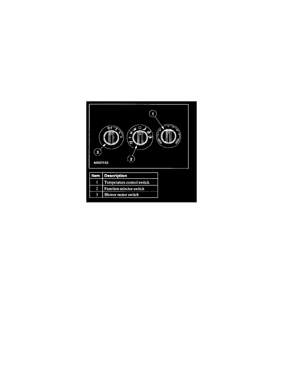
The climate control assembly has three system controls:
^
The A/C heater function selector switch combines a vacuum selector valve with two electrical switches to supply battery positive voltage (B+) to
the A/C clutch circuit and the blower motor control circuit.
^
The temperature selection is accomplished through cable-controlled positioning of the temperature blend door located in the heater core housing.
^
The blower motor switch controls the blower motor speed by adding or bypassing resistors in the heater blower motor switch resistor.