
Escape 2WD L4-122 2.0L DOHC VIN B SFI (2001)
Courtesy Lamp: Initial Inspection and Diagnostic Overview
1. Verify the customer concern by operating the system.
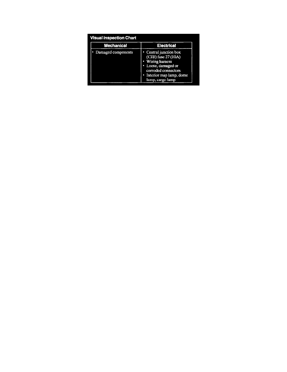
2. Visually inspect for obvious signs of mechanical and electrical damage.
Visual Inspection Chart
3. If an obvious cause for an observed of reported concern is found, correct the cause (if possible) before proceeding to the next step.
4. If the diagnostic tool does not power up, refer to the diagnostic tool manual.
5. Carry out the DATA LINK DIAGNOSTICS test. See: Powertrain Management/Computers and Control Systems/Module Communication
Network/Testing and Inspection/Module Communications Network/Pinpoint Tests/Pinpoint Test PC (Precheck)
If the diagnostic tool responds with:
^
CKT914, CKT915 or CKT70 = ALL ECUS NO RESP/NOT EQUIP, refer to Module Communications Network (Information Bus).
^
NO RESP/NOT EQUIP for GEM, Refer to Multifunction Electronic Control Module (General Module).
^
SYSTEM PASSED, retrieve and record the continuous Diagnostic Trouble Codes (DTCs), erase the continuous DTCs, and carry out the
self-test diagnostics for the GEM.
6. If the DTCs retrieved are related to the concern, go to the GEM Diagnostic Trouble Code (DTC) Index to continue diagnostics. See: Diagnostic
Trouble Code Descriptions
7. If no DTCs related to the concern are retrieved, proceed to the Symptom Chart to continue diagnostics. See: Symptom Related Diagnostic
Procedures
8. If the DTCs are retrieved that are not found in the following GEM Diagnostic Trouble Code (DTC) Index, refer to the master GEM Diagnostic
Trouble Code (DTC) Index in Multifunction Electronic Control Module (General Module).