
Escape 2WD L4-2.5L (2009)
-
Disconnect: IC C220.
-
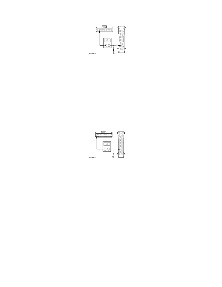
Measure the resistance between the interior rear view mirror C9012-6, circuit VMC31 (YE/GN), harness side and the IC C220-16, circuit VMC31
(YE/GN), harness side; and between the interior rear view mirror C9012-6, circuit VMC31 (YE/GN), harness side and ground.
-
Is the resistance less than 5 ohms between the interior rear view mirror and the IC, and greater than 10,000 ohms between the interior
rear view mirror and ground?
Yes
GO to A6.
No
REPAIR the circuit. CLEAR the DTCs. REPEAT the self-test.
-------------------------------------------------
A6 CHECK CIRCUIT VMC30 (BU/GY) FOR AN OPEN OR A SHORT TO GROUND
-
Measure the resistance between the interior rear view mirror C9012-7, circuit VMC30 (BU/GY), harness side and the IC C220-17, circuit VMC30
(BU/GY), harness side; and between the interior rear view mirror C9012-7, circuit VMC30 (BU/GY), harness side and ground.
-
Is the resistance less than 5 ohms between the interior rear view mirror and the IC, and greater than 10,000 ohms between the interior
rear view mirror and ground?
Yes
GO to A7.
No
REPAIR the circuit. CONNECT the negative battery cable. CLEAR the DTCs. REPEAT the self-test.
-------------------------------------------------
A7 CHECK FOR DTC U2013
-
Connect: Negative Battery Cable.
-
Connect: IC C220.
-
Connect: Interior Rear View Mirror C9012.
-
Ignition ON.
-
Clear the DTCs.
-
Ignition OFF.
-
Ignition ON.
-
Wait 10 seconds.
-
Retrieve the IC DTCs.
-
Is DTC U2013 present?
Yes
INSTALL a new interior rear view mirror. ADJUST the zone setting. REFER to Compass Zone Adjustment See: Adjustments/Compass Zone