
Escape 2WD L4-2.5L (2009)
GO to B2.
No
CHECK the Smart Junction Box (SJB) fuse 35 (10A). If OK, REPAIR the circuit. TEST the system for normal operation.
-------------------------------------------------
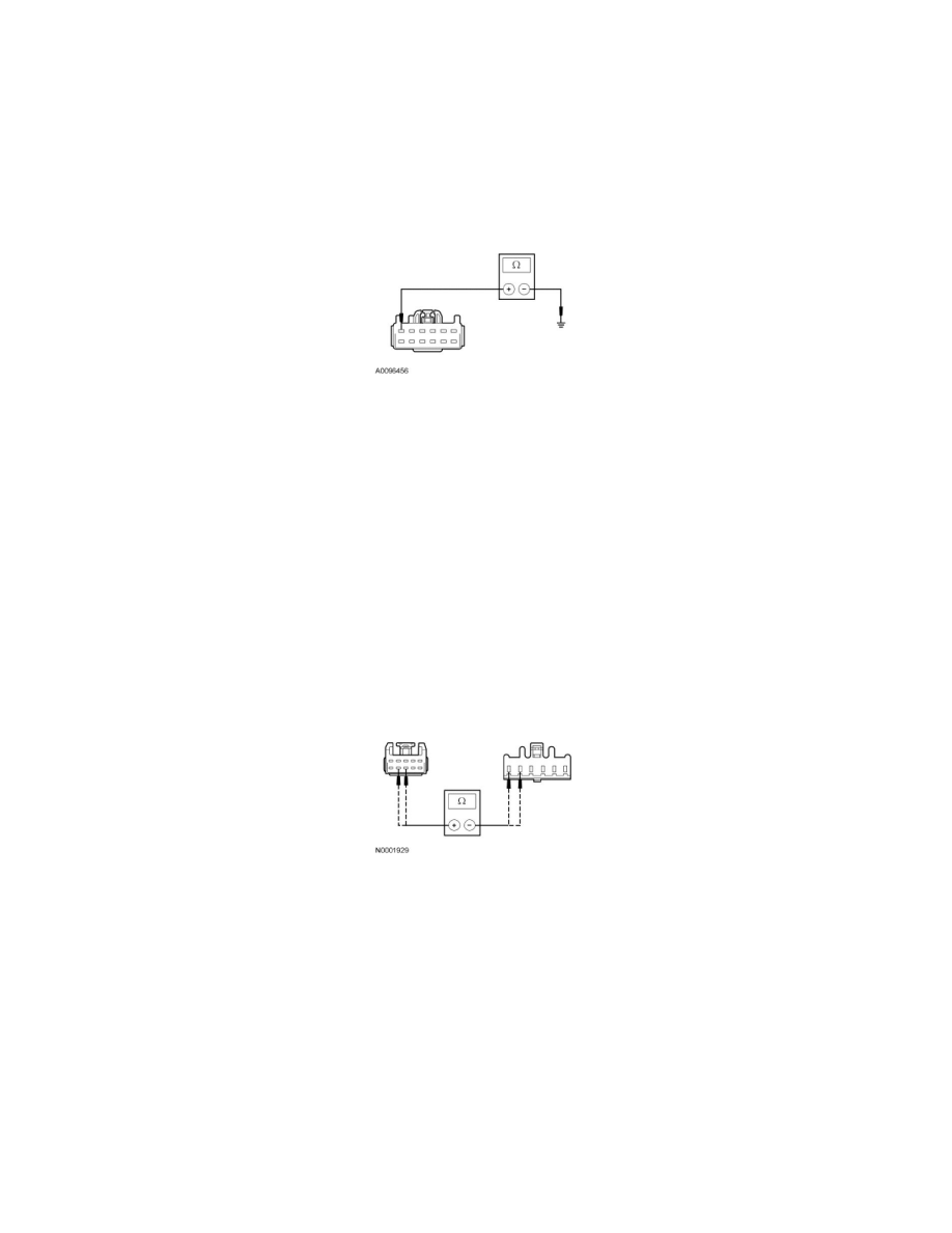
B2 CHECK CIRCUIT GD182 (BK/GY) FOR AN OPEN
-
Ignition OFF.
-
Measure the resistance between DC/AC inverter C2293a-6, circuit GD182 (BK/GY), harness side and ground.
-
Is the resistance less than 5 ohms?
Yes
GO to B3.
No
REPAIR the circuit. TEST the system for normal operation.
-------------------------------------------------
B3 CHECK CIRCUITS LYA03 (YE/VT) AND RYA03 (BU/BN) FOR AN OPEN
-
Disconnect: DC/AC Inverter C2293b.
-
Disconnect: AC Power Point C2292.
-
Measure the resistance between DC/AC inverter C2293b-9, circuit LYA03 (YE/VT), harness side and AC power point C2292-6 circuit LYA03
(YE/VT), harness side; and between DC/AC inverter C2293b-8, circuit RYA03 (BU/BN), harness side and AC power point C2292-5 circuit
RYA03 (BU/BN), harness side.
-
Are the resistances less than 5 ohms?
Yes
GO to B4.
No
REPAIR the circuit(s). TEST the system for normal operation.
-------------------------------------------------
B4 CHECK THE AC POWER POINT LED
-
Test the diode between AC power point C2292-5, component side and AC power point C2292-6, component side in both directions.