
Escape 2WD L4-2.5L Hybrid (2010)
Compass: Initial Inspection and Diagnostic Overview
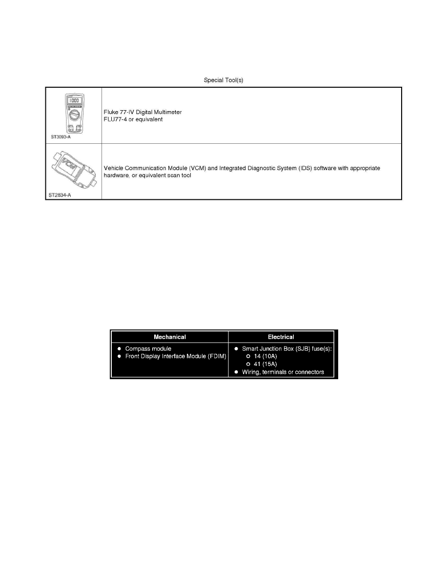
Special Tools Used With Diagnostics
Electronic Compass
Inspection and Verification
Electronic Compass
Inspection and Verification
NOTE: The Smart Junction Box (SJB) is also known as the Generic Electronic Module (GEM).
1. Verify the customer concern.
2. Visually inspect for obvious signs of mechanical or electrical damage.
Visual Inspection Chart
3. If an obvious cause for an observed or reported concern is found, correct the cause (if possible) before proceeding to the next step.
4. NOTE: Make sure to use the latest scan tool software release.
If the cause is not visually evident, connect the scan tool to the Data Link Connector (DLC).
5. NOTE: The Vehicle Communication Module (VCM) prove-out confirms power and ground from the DLC are provided to the VCM.
If the scan tool does not communicate with the VCM:
-
Check the VCM connection to the vehicle.
-
Check the scan tool connection to the VCM.
-
Refer to Information Bus, No Power To The Scan Tool, to diagnose no power to the scan tool.
6. If the scan tool does not communicate with the vehicle:
-
Verify the ignition key is in the ON position.
-
Verify the scan tool operation with a known good vehicle.