
Escape 4WD L4-2.5L Hybrid (2009)
Variable Valve Timing Actuator: Description and Operation
Variable Camshaft Timing (VCT) System
Overview
The intake phase shifting (IPS) VCT system enables rotation of the intake camshaft relative to the crankshaft rotation as a function of engine operating
conditions.
The VCT system has several operational modes: idle, part throttle, wide open throttle (WOT), and default mode. At idle and low engine speeds with
closed throttle, the powertrain control module (PCM) determines the phase angle based on a constant angle, limited by engine oil temperature and engine
RPM. At part and wide open throttle the PCM determines the phase angle based on engine RPM, load, and throttle position. VCT systems provide
reduced emissions and enhanced engine power, fuel economy and idle quality. IPS systems also have the added benefit of improved torque.
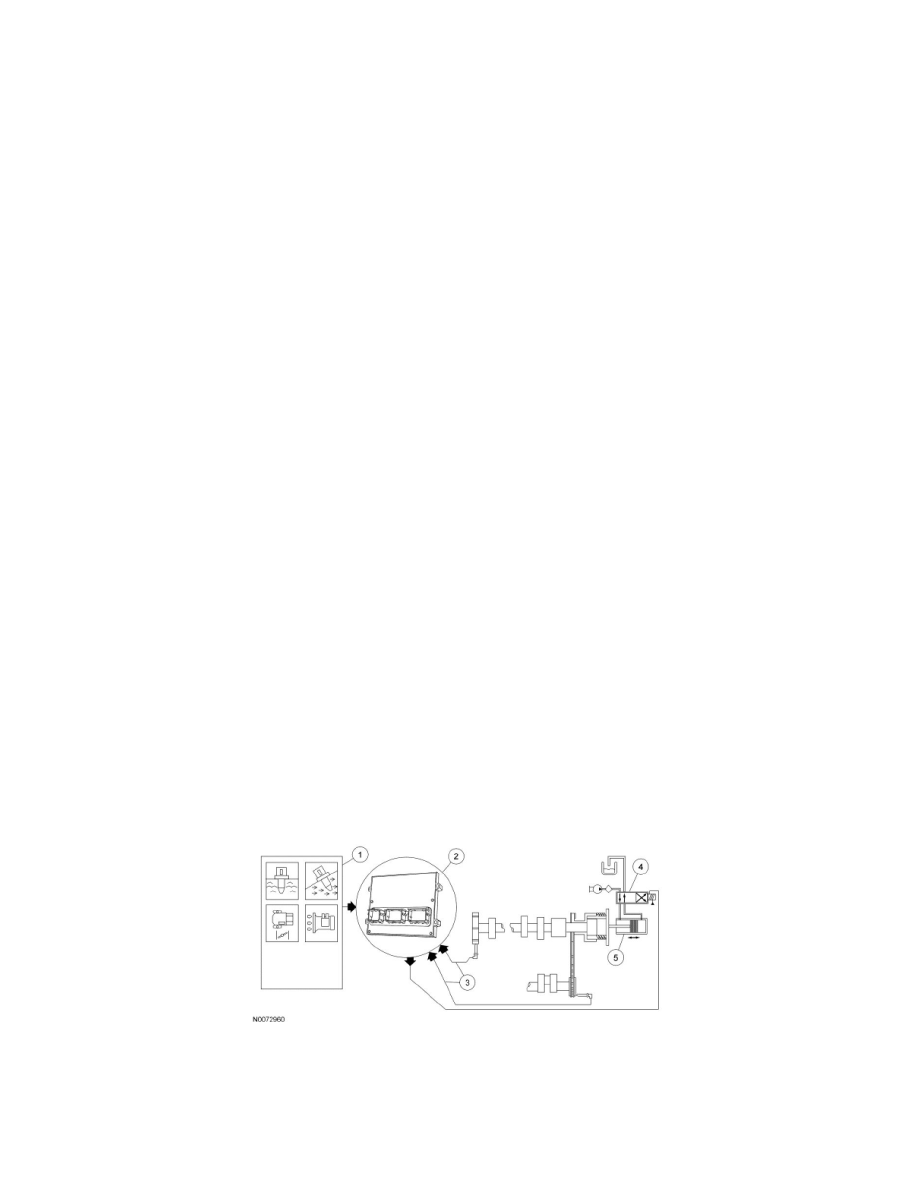
Variable Camshaft Timing (VCT) System
The VCT system consists of an electric hydraulic positioning control solenoid, a camshaft position (CMP) sensor, and a trigger wheel. The CMP trigger
wheel indicates the CMP signal for that bank. A crankshaft position (CKP) sensor provides the PCM with crankshaft positioning information in 10
degree increments.
1. The PCM receives input signals from the intake air temperature (IAT), cylinder head temperature (CHT), CMP, accelerator pedal position (APP)
sensor (via requested torque), mass air flow (MAF), and CKP sensors to determine the operating conditions of the engine. At idle and low engine
speeds with closed throttle, the PCM controls the camshaft position based on engine oil temperature and engine speed inputs. During cold start
emissions reduction mode, the camshaft position is determined via engine speed and estimates of engine coolant temperature and catalyst
temperature (estimated from other sensors already used such as IAT/CHT/MAF/CKP). During part and wide open throttle, the camshaft position is
determined by engine RPM, load and accelerator pedal position. The VCT system does not operate until the engine is at normal operating oil
temperature.
2. The VCT system is enabled by the PCM when the correct conditions are met.
3. The CKP signal is used as a reference for CMP positioning.
4. The VCT solenoid valve is an integral part of the VCT system. The solenoid valve controls the flow of engine oil in the VCT actuator assembly.
As the PCM controls the duty cycle of the solenoid valve, oil pressure/flow advances or retards the cam timing. Duty cycles near 0% or 100%
represent rapid movement of the camshaft. Retaining a fixed camshaft position is accomplished by dithering (oscillating) the solenoid valve duty
cycle.
The PCM calculates and determines the desired camshaft position. It continually updates the VCT solenoid duty cycle until the desired position is
achieved. A difference between the desired and actual camshaft position represents a position error in the PCM VCT control loop. The PCM
disables the VCT and places the camshaft in a default position if a concern is detected. A related diagnostic trouble code (DTC) is also set when
the concern is detected.
5. When the VCT solenoid is energized, engine oil is allowed to flow to the VCT actuator assembly which advances or retards the camshaft timing.
One half of the VCT actuator is coupled to the camshaft and the other half is connected to the timing chain. Oil chambers between the two halves
couple the camshaft to the timing chain. When the flow of oil is shifted from one side of the chamber to the other, the differential change in oil
pressure forces the camshaft to rotate in either an advance or retard position depending on the oil flow.
VCT System