
Escape 4WD L4-2.5L Hybrid (2009)
-------------------------------------------------
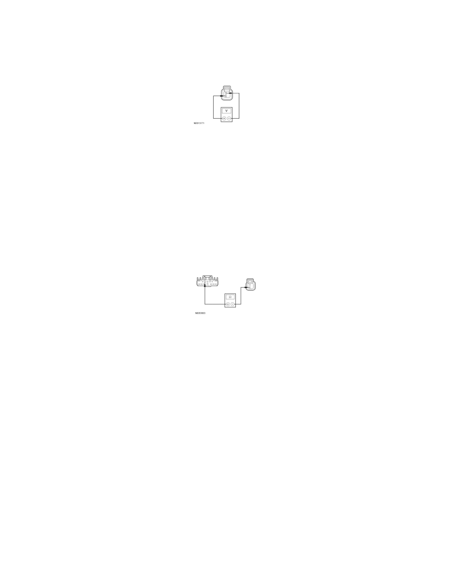
A8 CHECK CIRCUIT SRH01 (YE/RD) FOR VOLTAGE
-
Connect: Negative Battery Cable.
-
Measure the voltage between the horn C1101-2, circuit SRH01 (YE/RD), harness side, and the horn C1101-1, circuit GD120 (BK/GN), harness
side, while pressing the horn switch.
-
Is the voltage greater than 10 volts?
Yes
INSTALL a new horn. REFER to Horn See: Service and Repair. TEST the system for normal operation.
No
VERIFY the SJB fuse 24 (20A) is OK. If OK, GO to A9. If not OK, REFER to the Wiring Diagrams to identify the possible causes of the circuit short.
-------------------------------------------------
A9 CHECK CIRCUIT SRH01 (YE/RD) FOR AN OPEN
-
Disconnect: SJB C2280e.
-
Measure the resistance between the SJB C2280e-5, circuit SRH01 (YE/RD), harness side, and the horn C1101-2, circuit SRH01 (YE/RD), harness
side.
-
Is the resistance less than 5 ohms?
Yes
GO to A10.
No
REPAIR the circuit. TEST the system for normal operation.
-------------------------------------------------
A10 CHECK FOR CORRECT SJB OPERATION
-
Disconnect all the SJB connectors.
-
Check for:
-
corrosion
-
damaged pins
-
pushed-out pins
-
Connect all the SJB connectors and make sure they seat correctly.
-
Operate the system and verify the concern is still present.
-
Is the concern still present?
Yes
INSTALL a new SJB. TEST the system for normal operation.
No
The system is operating correctly at this time. The concern may have been caused by a loose or corroded connector.