
Escape 4WD L4-2.5L Hybrid (2009)
REPAIR the circuit. CONNECT the negative battery cable. CLEAR the DTCs. REPEAT the network test with the scan tool.
-------------------------------------------------
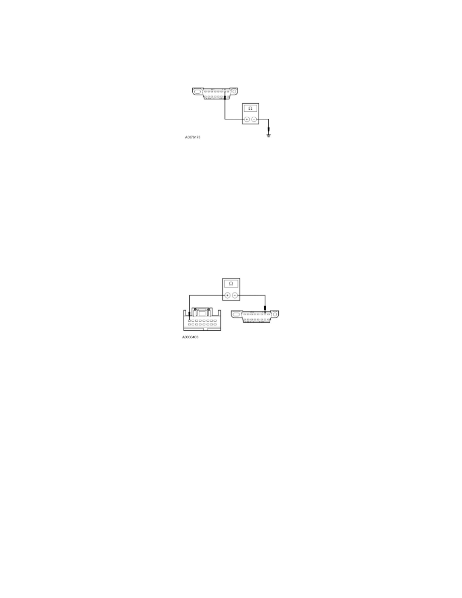
Q5 CHECK THE ISO 9141 CIRCUIT FOR A SHORT TO GROUND
-
Measure the resistance between the DLC C251-7, circuit VDB10 (GY), harness side and ground.
-
Is the resistance greater than 10,000 ohms?
Yes
GO to Q6.
No
REPAIR the circuit. CONNECT the negative battery cable. CLEAR the DTCs. REPEAT the network test with the scan tool.
-------------------------------------------------
Q6 CHECK THE ISO 9141 COMMUNICATIONS NETWORK CIRCUIT BETWEEN THE PAM AND THE DLC FOR AN OPEN
-
Measure the resistance between the PAM C4014-8, circuit VDB10 (GY), harness side and the DLC C251-7, circuit VDB10 (GY), harness side.
-
Is the resistance less than 5 ohms?
Yes
CONNECT the negative battery cable. GO to Q7.
No
REPAIR the circuit. CONNECT the negative battery cable. CLEAR the DTCs. REPEAT the network test with the scan tool.
-------------------------------------------------
Q7 CHECK FOR CORRECT PAM OPERATION
-
Disconnect the PAM connector.
-
Check for:
-
corrosion
-
damaged pins
-
pushed-out pins
-
Connect the PAM connector and make sure it seats correctly.
-
Operate the system and verify the concern is still present.
-
Is the concern still present?
Yes
INSTALL a new PAM. CLEAR the DTCs. REPEAT the network test with the scan tool.
No