
Escape 4WD L4-2.5L Hybrid (2009)
If the vehicle is equipped with a Satellite Digital Audio Receiver System (SDARS) module, GO to U20.
If the vehicle is not equipped with a SDARS module, GO to U21.
-------------------------------------------------
U20 CHECK THE MS-CAN (+) AND MS-CAN (-) CIRCUITS FOR A SHORT TO GROUND WITH THE SDARS MODULE
DISCONNECTED
-
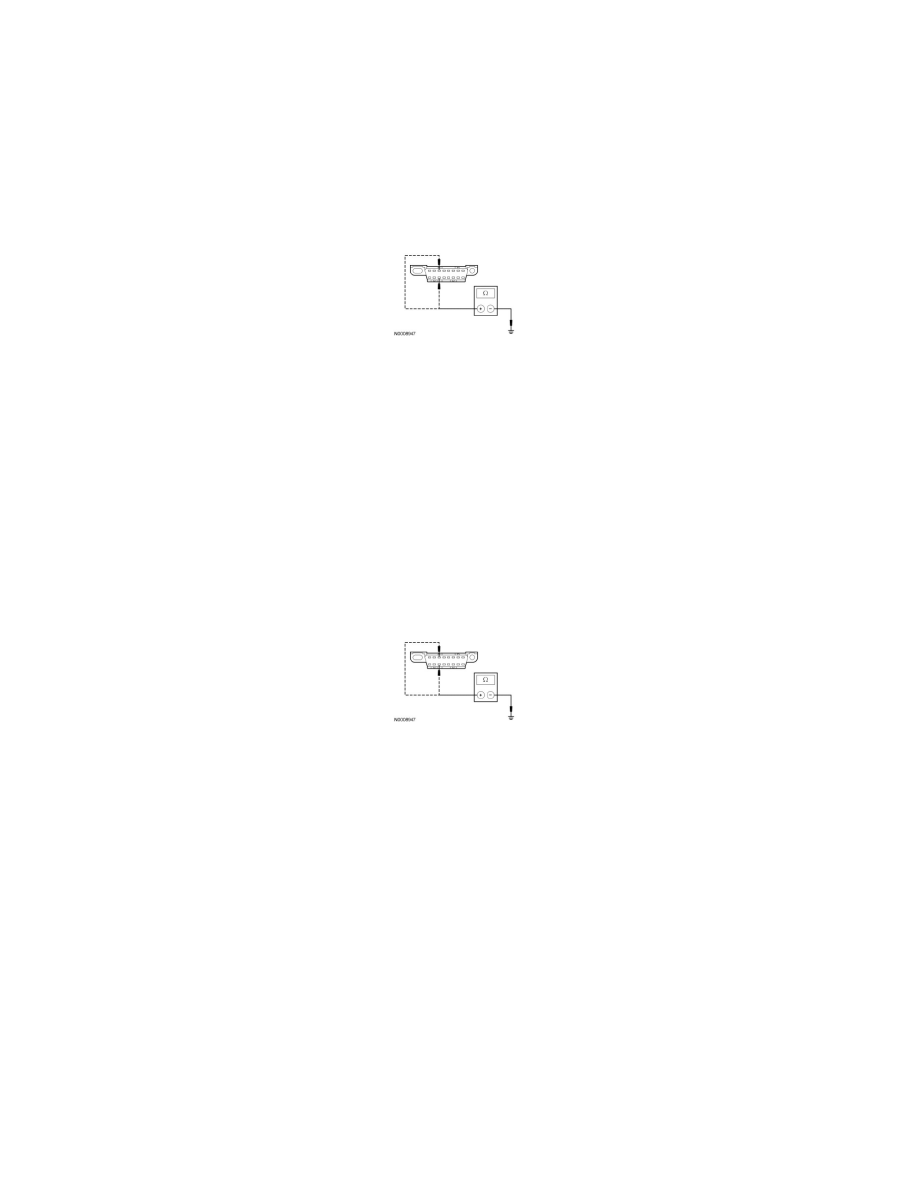
Disconnect: SDARS Module C3290.
-
Measure the resistance between the DLC C251-3, circuit VDB06 (GY/OG), harness side and ground; and between the DLC C251-11, circuit
VDB07 (VT/OG), harness side and ground.
-
Are the resistances greater than 1,000 ohms?
Yes
CONNECT the negative battery cable. GO to U28.
No
GO to U21.
-------------------------------------------------
U21 CHECK THE MS-CAN (+) AND MS-CAN (-) CIRCUITS FOR A SHORT TO GROUND WITH THE FDIM DISCONNECTED
-
Disconnect: FDIM C2123.
-
Measure the resistance between the DLC C251-3, circuit VDB06 (GY/OG), harness side and ground; and between the DLC C251-11, circuit
VDB07 (VT/OG), harness side and ground.
-
Are the resistances greater than 1,000 ohms?
Yes
CONNECT the negative battery cable. GO to U29.
No
If the vehicle is equipped with a Front Controls Interface Module (FCIM), GO to U22.
If the vehicle is not equipped with an FCIM, GO to U23.
-------------------------------------------------
U22 CHECK THE MS-CAN (+) AND MS-CAN (-) CIRCUITS FOR A SHORT TO GROUND WITH THE FCIM DISCONNECTED
-
Disconnect: FCIM C2402.
-
Measure the resistance between the DLC C251-3, circuit VDB06 (GY/OG), harness side and ground; and between the DLC C251-11, circuit
VDB07 (VT/OG), harness side and ground.