
Escape 4WD V6-3.0L (2008)
CAUTION: Electronic modules are sensitive to static electrical charges. The anti-lock brake system (ABS) module can be damaged if exposed
to these charges.
NOTE: When installing a new ABS module/hydraulic control unit (HCU) assembly, it must be configured (either by download/upload or uploading
the as-built data method).
NOTE: On vehicles equipped with roll stability control (RSC), the ABS module is available separately from the HCU and should be serviced
separately. However, if the RSC equipped vehicle requires a new HCU, then the ABS module and the HCU must be installed as an assembly. Make
sure to use the most recently released service parts.
All vehicles
1. Disconnect the battery ground cable.
2. Remove the air cleaner and the air cleaner outlet pipe.
3. Disconnect the master cylinder brake tube fittings from the hydraulic control unit (HCU).
^
To install, tighten to 23 Nm (17 lb-ft).
Vehicles with 3.0L engine
4. Disconnect the master cylinder brake tube fittings from the master cylinder and remove the brake tubes.
^
To install, tighten to 23 Nm (17 lb-ft).
All vehicles
5. NOTE: The brake tubes must be installed in the same location as removed.
Disconnect the front brake tube fittings from the HCU.
^
To install, tighten to 15 Nm (11 lb-ft).
6. Disconnect the rear brake tube fittings from the jumper tubes.
^
To install, tighten to 15 Nm (11 lb-ft).
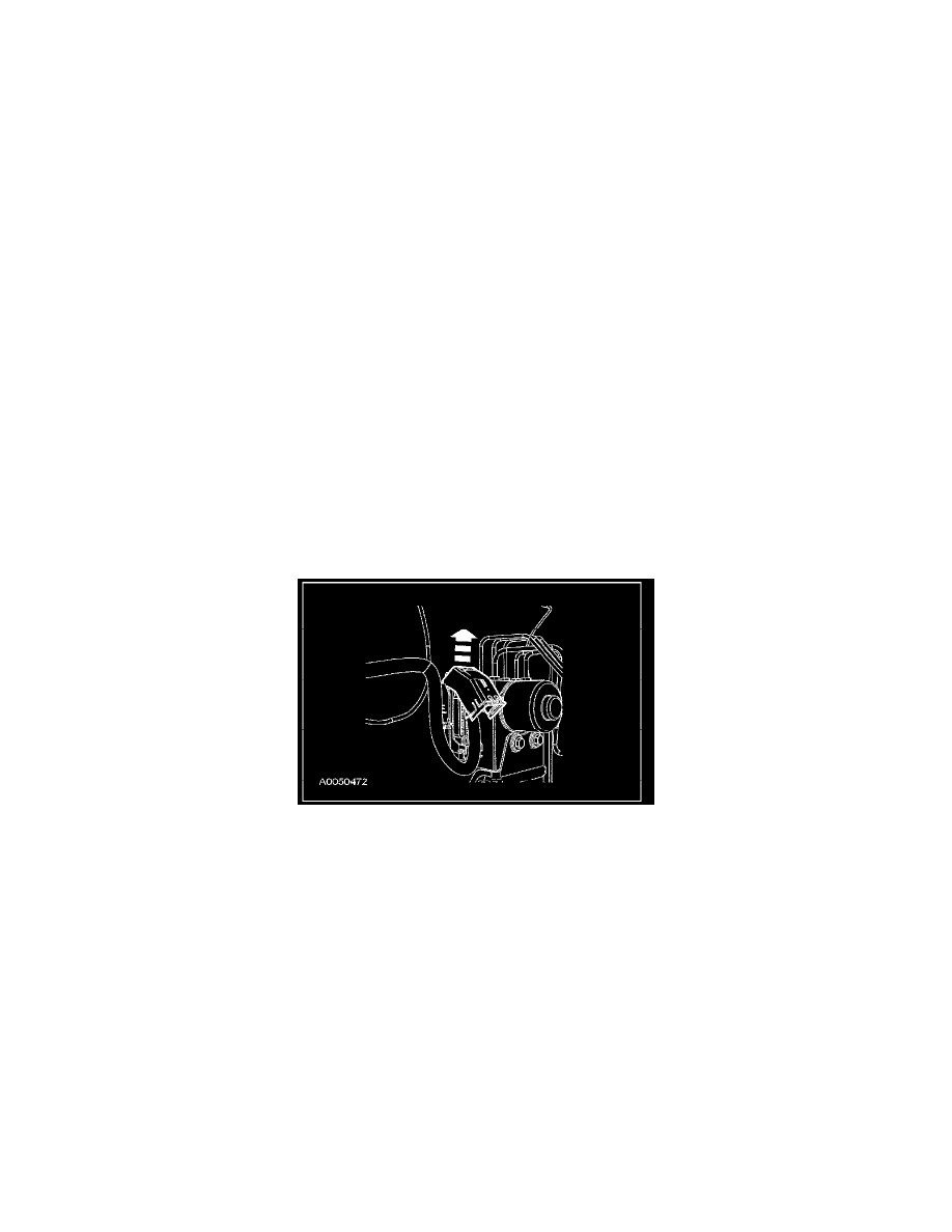
7. Disconnect the electrical connector by rotating the protective cover.
8. Remove the 3 HCU bracket-to-frame bolts and remove the HCU.
^
To install, tighten to 20 Nm (15 lb-ft).
9. To install, reverse the removal procedure.
^
Bleed the brake system.