
Escape 4WD V6-3.0L (2008)
6. Remove the stud and position the generator away from the engine.
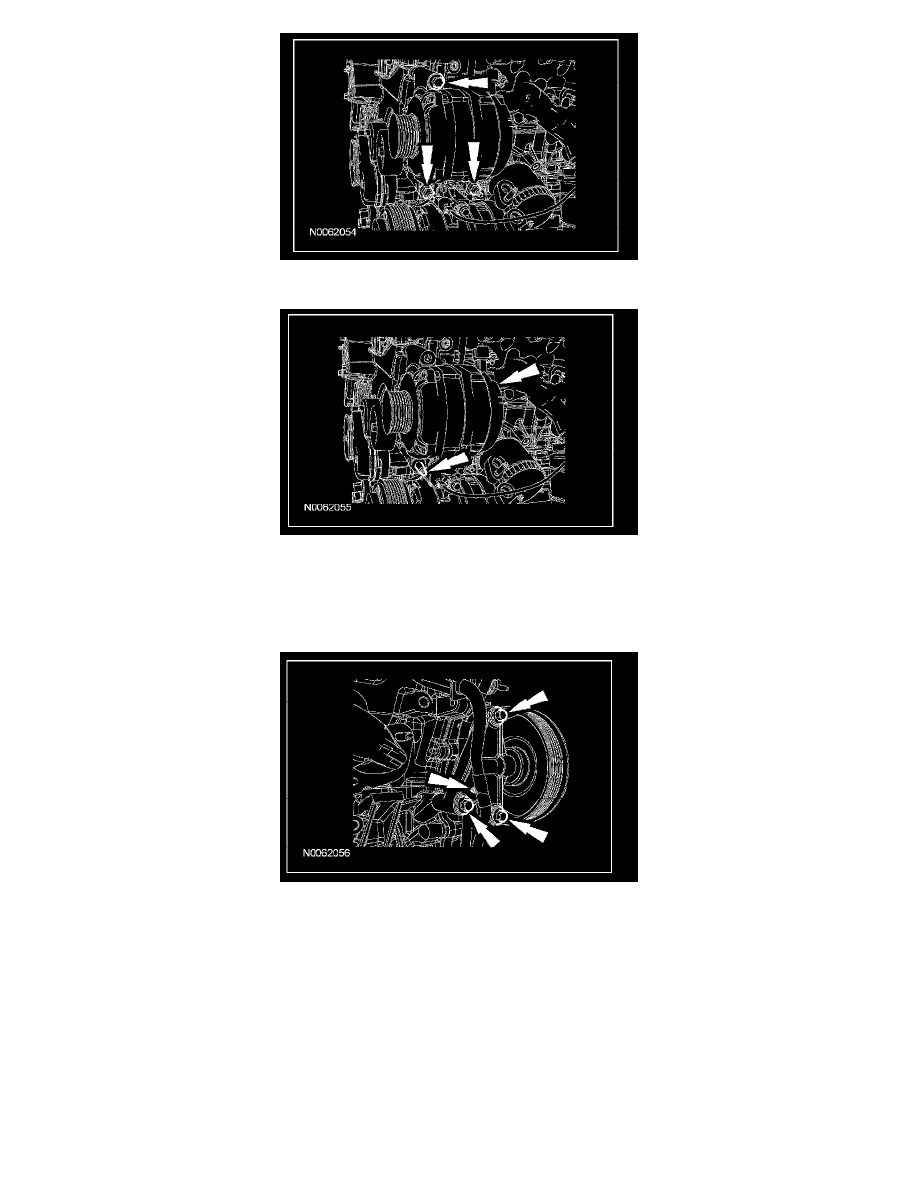
7. Remove the bolt and the accessory drive belt tensioner.
8. Remove the bolt and the LH accessory drive belt idler pulley.
9. Remove the bolt and the center accessory drive belt idler pulley.
10. Remove the 3 RH accessory drive belt idler pulley and bracket bolts.
^
Detach the wiring harness retainer and remove the idler pulley assembly.
11. Detach the wiring harness retainer, remove the nut and the catalyst monitor sensor electrical connector bracket.
12. Disconnect the crankshaft position (CKP) sensor electrical connector.
13. Disconnect the camshaft position (CMP) sensor electrical connector.
14. Remove the LH and RH valve covers.
15. Remove the engine support insulator.
16. Disconnect the A/C pressure switch electrical connector.
17. Detach the 2 wire harness retainers from the speed control actuator mounting studs.
18. Remove the 3 nuts and position the speed control actuator aside.
19. Remove the 2 oil pan-to-front cover bolts.
20. Remove the 14 bolts, 2 stud bolts and the engine front cover.
^
Remove and discard the gaskets.
Installation