
Escape 4WD V6-3.0L (2008)
Removal and Installation
WARNING: Do not use any fluid other than clean brake fluid meeting manufacturer's specification. Additionally, do not use brake fluid that
has been previously drained. Following these instructions will help prevent system contamination, brake component damage and the risk of
serious personal injury.
WARNING: Carefully read cautionary information on product label. For EMERGENCY MEDICAL INFORMATION seek medical advice.
In the USA or Canada on Ford/Motorcraft products call: 1-800-959-3673. For additional information, consult the product Material Safety
Data Sheet (MSDS) if available. Failure to follow these instructions may result in serious personal injury.
CAUTION: Brake fluid is harmful to painted and plastic surfaces. If brake fluid is spilled onto a painted or plastic surface, immediately wash
it with water.
CAUTION: Electronic modules are sensitive to static electrical charges. The anti-lock brake system (ABS) module can be damaged if exposed
to these charges.
NOTE: Do not swap ABS modules between vehicles, the ABS module and the hydraulic control unit (HCU) are calibrated as an assembly.
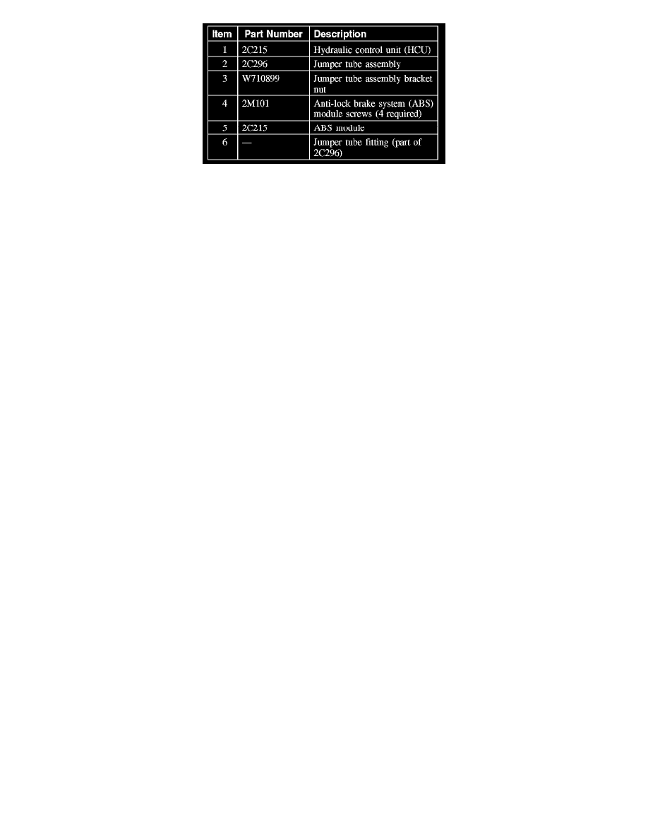
1. Remove the HCU.
2. Remove the jumper tube assembly bracket nut.
^
To install, tighten to 9 Nm (80 lb-inch).
3. Disconnect the jumper tubes fittings from the HCU and remove the jumper tube assembly.
^
To install, tighten to 15 Nm (11 lb-ft).
4. Remove the 4 ABS module screws and the ABS module.
^
To install, tighten to 2 Nm (18 lb-inch).
5. To install, reverse the removal procedure.
6. Configure the ABS module.
7. NOTE: Vehicle must be on level ground and at a complete stand still during calibration.
Calibrate the ABS module. Follow the instructions on the scan tool.