
Escort L4-116 1.9L VIN 9 2-bbl (1986)
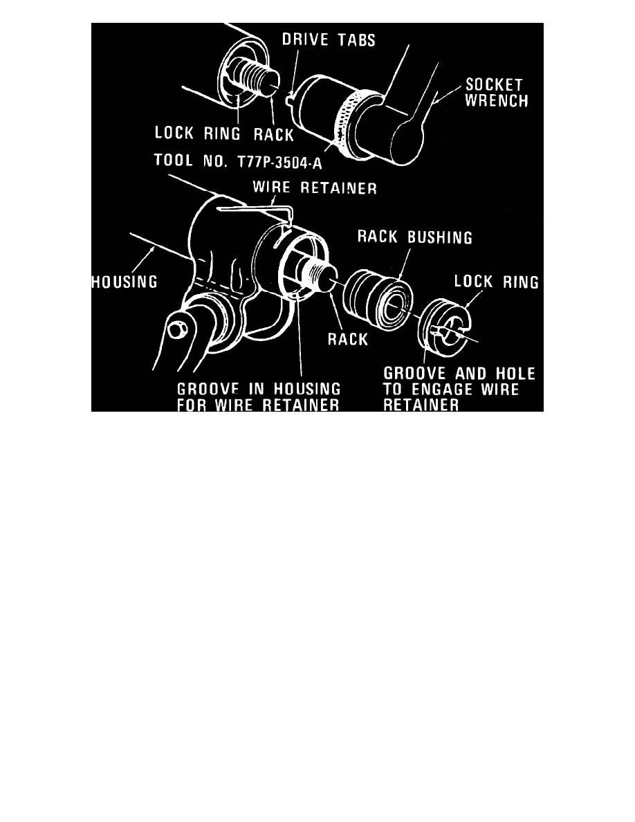
Fig. 22 Installing rack bushing lock ring. 1982 Capri, Mustang & 1984---86 Mustang SVO
10.
Using lock ring wrench tool No. T77P-3504-A, or equivalent, with drive tabs engaged in the end plate slots, push in end plate until end plate
retainer wire groove is visible through the rack cylinder slot. Rotate end plate to line up the retainer wire hole with the cylinder slot, insert bent end
of the retainer wire in the wire hole and rotate end plate clockwise until the retainer wire is fully engaged. Turn an additional 180 degrees, Fig. 22.
11.
Install tie rod ball sockets as described previously.
12.
Install input shaft and valve assembly as described previously.
13.
Install yoke bearing, spring, plug and locknut. Prior to torquing locknut, adjust yoke bearing preload as described under ``Rack Yoke Bearing
Preload Adjustment.''
14.
Install bellows and tie rod ends.
Repair & Inspection
TIE RODS & BELLOWS
Disassembly
1.
Clean exterior of gear assembly.
2.
Loosen jam nuts and remove tie rod ends and jam nuts.
3.
Remove bellows clamps and the small (outer) tie rod clamps. Discard bellows clamps.
4.
Remove the bellows.
5.
Cycle gear to full right turn to expose rack teeth. Mount rack teeth in soft jawed vise to remove either or both tie rod ends.
6.
Remove tie rod ends by turning ball socket with pipe wrench.
7.
Check rack for corrosion and contamination. If either is present, the gear must be completely overhauled or replaced.
Assembly
1.
Cycle gear to full right turn to expose rack teeth. Mount rack teeth in a soft jawed vise.
2.
Before installing tie rods, inspect ends of rack for flatness. If burrs are present, remove by lightly filing.
3.
Install service tie rods and torque to 35---50 ft. lbs.
4.
Remove gear assembly from vise.
5.
Support ball socket, and stake to rack using a stake punch. Center of stake punch should be approximately 1.5 mm (.06 inch) away from rack end.
Perform visual inspection to verify displacement of metal into rack slot.
6.
Replenish any grease that may have been removed with fresh grease by applying it to the rack teeth. Coat remainder of rack (both ends) with a
light film of grease. Use specified steering gear lubricant.