
Escort L4-98 1.6L SOHC VIN 5 FI (1985)
Engine Control Module: Description and Operation
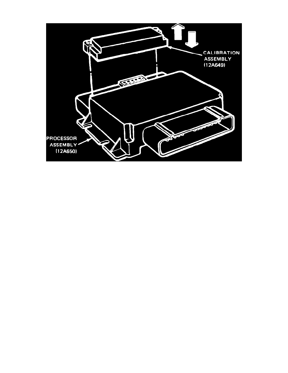
Fig. 6 Electronic control assembly (ECA)
The ECA is the brain of the EEC-IV system and is comprised of a processor and calibration assembly, Fig. 6. The processor receives input signals
from the various sensors. The information obtained is used by the processor to activate engine control systems to obtain optimum emission control and
engine performance
The calibration assembly is a permanent memory device that contains information. The processor applies the sensor inputs to the stored information to
determine when and how long the various control systems should be applied.