
Expedition 2WD V8-5.4L (2009)
6. Connect the intake manifold vacuum tube to the support bracket and the valve cover stud.
7. Connect the brake booster vacuum hose to the intake manifold vacuum tube.
8. Connect the 4 LH ignition coil and the LH VCT solenoid electrical connectors and attach the 2 engine wiring harness retainers to the LH valve
cover studs.
9. Connect the heated PCV element electrical connector.
10. Connect the TP sensor and ETC electrical connectors.
11. Connect the 8 fuel injector electrical connectors.
12. Connect the heater coolant hose to the coolant crossover manifold assembly.
13. Connect the upper radiator hose to the thermostat housing.
14. Connect the EVAP canister purge valve electrical connector and the EVAP tube quick connect coupling to the EVAP canister purge valve.
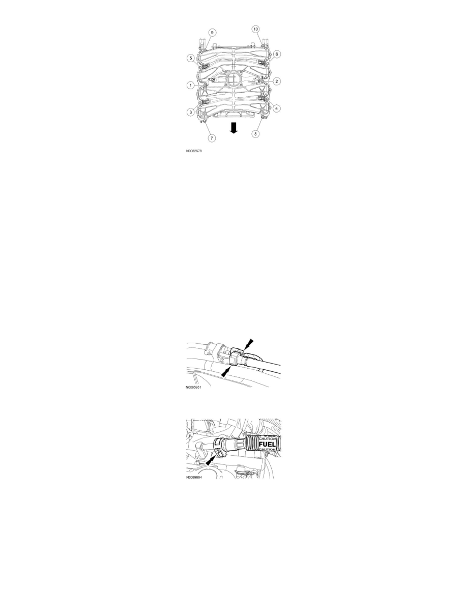
15. Connect the fuel supply tube quick connect coupling.
16. Position the PCV tube and connect the quick connect couplings.
17. Position the TB-to-ACL outlet pipe adapter and install the 3 bolts.
-
Tighten to 10 Nm (89 lb-in).
18. Position the air intake resonator assembly, install the bolt and the clamp.
-
Tighten the bolt to 10 Nm (89 lb-in).
19. Position the crankcase vent tube and connect the quick connect couplings.
20. Install the generator.