
Expedition 2WD V8-5.4L (2009)
The No. 1 cylinder camshaft exhaust lobe must be coming up on the exhaust stroke. Verify by noting the position of the 2 intake camshaft lobes
and the exhaust lobe on the No. 1 cylinder.
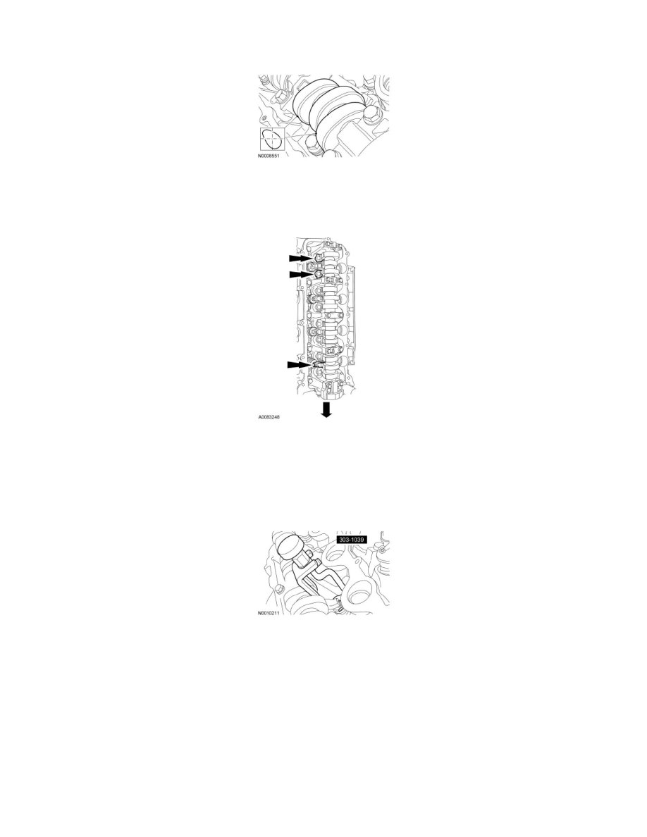
5. NOTICE: If the components are to be reinstalled, they must be installed in the same positions. Mark the components for installation into
their original locations. Failure to follow these instructions may result in engine damage.
Remove only the 3 camshaft roller followers shown in the illustration from the RH cylinder head.
6. NOTE: Do not allow the valve keepers to fall off of the valve or the valve may drop into the cylinder. If a valve drops into the cylinder, the
cylinder head must be removed. For additional information, refer to Cylinder Head See: Cylinder Head Assembly/Service and Repair/Removal
and Replacement/Cylinder Head - Removal.
NOTE: It may be necessary to push the valve down while compressing the spring.
Using the Valve Spring Compressor, remove the 3 designated camshaft roller followers in the previous step from the RH cylinder head.
7. NOTICE: If the components are to be reinstalled, they must be installed in the same positions. Mark the components for installation into
their original locations. Failure to follow these instructions may result in engine damage.
Remove only the 3 camshaft roller followers shown in the illustration from the LH cylinder head.