
Expedition 2WD V8-5.4L (2009)
J1 DETERMINE THE INOPERATIVE STOPLAMP
-
Ignition OFF.
-
Apply the brake pedal and observe the stoplamps.
-
Are all the stoplamps inoperative?
Yes
Go To Pinpoint Test I See: Pinpoint Test I: All The Stoplamps Are Inoperative
No
For the high mounted stoplamp, GO to J2.
If both sides (LH and RH rear stoplamps) are inoperative, VERIFY the SJB fuse 6 (20A) is OK. If OK, GO to J4. If not OK, REFER to the Wiring
Diagrams to identify the possible causes of the circuit short.
If only one side (the LH or RH rear stoplamp) is inoperative, GO to J5.
-------------------------------------------------
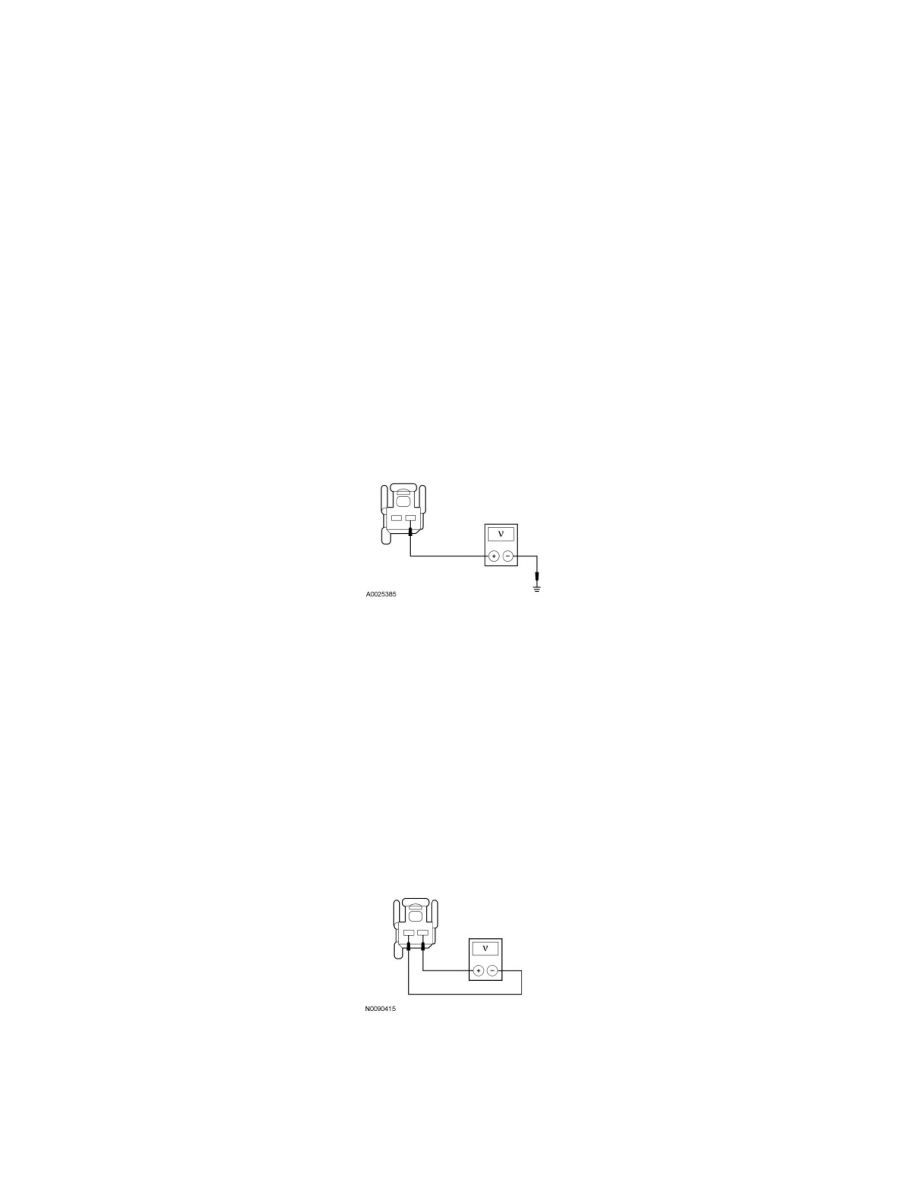
J2 CHECK FOR VOLTAGE TO THE HIGH MOUNTED STOPLAMP
-
Disconnect: High Mounted Stoplamp C475.
-
While applying the brake pedal, measure the voltage between the high mounted stoplamp C475-1, circuit CLS17 (YE/GY), harness side and
ground.
-
Is the voltage greater than 10 volts?
Yes
GO to J3.
No
REPAIR circuit CLS17 (YE/GY) for an open. TEST the system for normal operation.
-------------------------------------------------
J3 CHECK FOR VOLTAGE TO THE HIGH MOUNTED STOPLAMP USING THE CONNECTOR GROUND
-
While applying the brake pedal, measure the voltage between the high mounted stoplamp C475-1, circuit CLS17 (YE/GY), harness side and the
high mounted stoplamp C475-2, circuit GD150 (BK/WH), harness side.
-
Is the voltage greater than 10 volts?
Yes
INSTALL a new high mounted stoplamp. TEST the system for normal operation.
No