
Expedition 2WD V8-5.4L (2009)
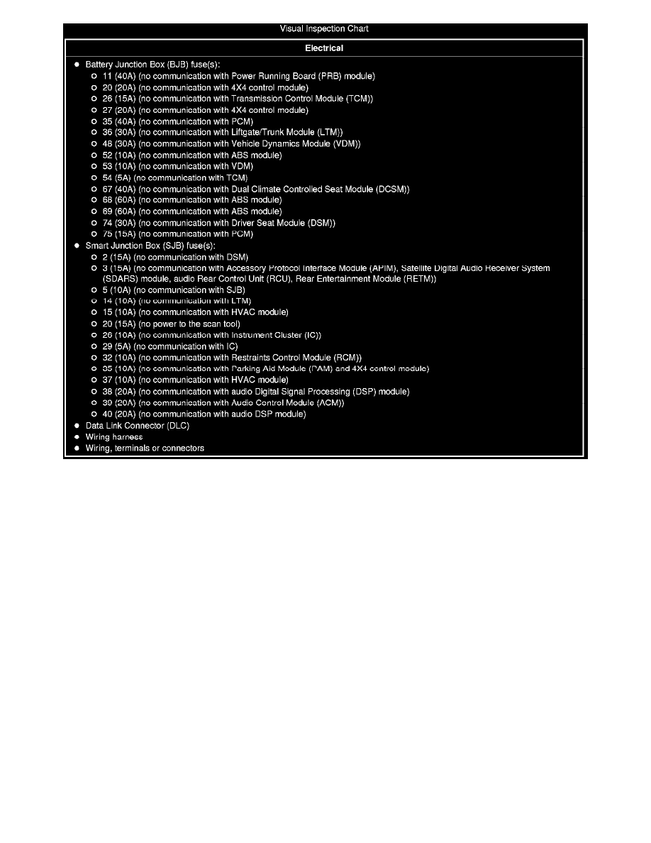
Visual Inspection Chart
3. Connect the scan tool to the DLC.
-
NOTE: Make sure to use the latest scan tool software release.
NOTE: The Vehicle Communication Module (VCM) LED prove-out confirms power and ground from the DLC are provided to the VCM.
If the Integrated Diagnostic System (IDS) does not communicate with the VCM:
-
Check the VCM connection to the vehicle.
-
Check the scan tool connection to the VCM.
-
Go To Pinpoint Test Y, to diagnose No Power To The Scan Tool. See: Pinpoint Tests/Pinpoint Test Y: No Power To The Scan Tool
4. Establish a scan tool session.
-
NOTE: The scan tool will first attempt to communicate with the PCM, after establishing communication with the PCM, the scan tool will then
attempt to communicate with all other modules on the vehicle.
If an IDS session cannot be established with the vehicle, (IDS may state "No communication can be established with the PCM"):
-
Choose "NO" when the scan tool prompts whether or not to retry communication.
-
Enter either a PCM part number, tear tag or calibration number to identify the vehicle and start a session (the PCM part number and
4-character tear tag are printed on the PCM label).
-
Go To Pinpoint Test A, to diagnose The PCM Does Not Respond To The Scan Tool. See: Pinpoint Tests/Pinpoint Test A: The PCM Does
Not Respond To The Scan Tool