
Expedition 2WD V8-5.4L (2009)
-
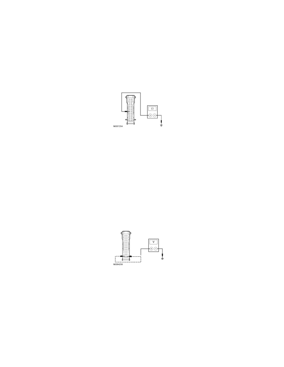
Is the resistance between 54 and 66 ohms?
Yes
GO to C2.
No
GO to C4.
-------------------------------------------------
C2 CHECK THE IC GROUND CIRCUIT FOR AN OPEN
-
Measure the resistance between the IC C220-6, circuit GD133 (BK), harness side and ground.
-
Is the resistance less than 5 ohms?
Yes
CONNECT the negative battery cable. GO to C3.
No
REPAIR the circuit. CONNECT the negative battery cable. CLEAR the DTCs. REPEAT the network test with the scan tool.
-------------------------------------------------
C3 CHECK THE IC VOLTAGE SUPPLY CIRCUITS FOR AN OPEN
-
Disconnect: IC C220.
-
Ignition ON.
-
Measure the voltage between the IC C220-1, circuit SBP26 (YE/RD) harness side and ground; and between the IC C220-14, circuit CBP29
(WH/VT) harness side and ground.
-
Are the voltages greater than 10 volts?
Yes
GO to C5.
No
VERIFY the SJB fuse 26 (10A) or fuse 29 (5A) is OK. If OK, REPAIR the circuit in question. If not OK, REFER to the Wiring Diagrams to identify the
possible causes of the circuit short. CLEAR the DTCs. REPEAT the network test with the scan tool.
-------------------------------------------------
C4 CHECK THE HS-CAN CIRCUITS BETWEEN THE IC AND THE DLC FOR AN OPEN
-
Measure the resistance between the IC C220-7, circuit VDB04 (WH/BU), harness side and the Data Link Connector (DLC) C251-6, circuit
VDB04 (WH/BU), harness side.