
Expedition 2WD V8-5.4L (2009)
-
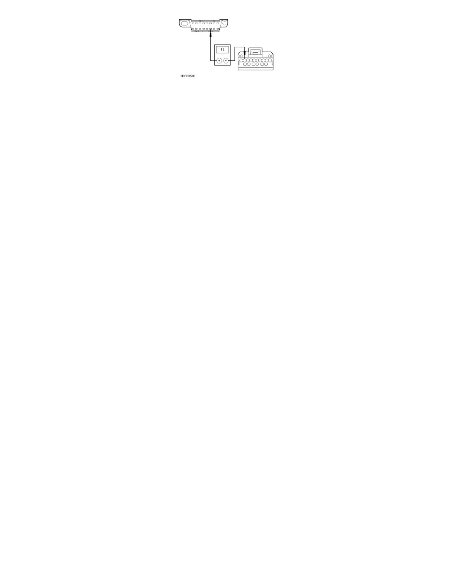
Are the resistances less than 5 ohms?
Yes
CONNECT the negative battery cable. GO to F4.
No
REPAIR the circuit in question. CONNECT the negative battery cable. CLEAR the DTCs. REPEAT the network test with the scan tool.
-------------------------------------------------
F4 CHECK FOR CORRECT VDM OPERATION
-
Disconnect all the VDM connectors.
-
Check for:
-
corrosion
-
damaged pins
-
pushed-out pins
-
Connect all the VDM connectors and make sure they seat correctly.
-
Operate the system and verify the concern is still present.
-
Is the concern still present?
Yes
INSTALL a new VDM. CLEAR the DTCs. REPEAT the network test with the scan tool.
No
The system is operating correctly at this time. The concern may have been caused by a loose or corroded connector. CLEAR the DTCs. REPEAT the
network test with the scan tool.
-------------------------------------------------
Pinpoint Test G: The Transmission Control Module (TCM) Does Not Respond To The Scan Tool
Communications Network
Pinpoint Tests
Pinpoint Test G: The Transmission Control Module (TCM) Does Not Respond To The Scan Tool
Refer to Wiring Diagram Set 14, Module Communications Network for schematic and connector information. See: Diagrams/Electrical
Diagrams/Diagrams By Number
Refer to Wiring Diagram Set 29, Transmission Controls for schematic and connector information. See: Diagrams/Electrical Diagrams/Diagrams By
Number
Normal Operation
The Transmission Control Module (TCM) communicates with the scan tool through the High Speed Controller Area Network (HS-CAN). Circuits
VDB04 (WH/BU) (HS-CAN +) and VDB05 (WH) (HS-CAN -) provide the network connection to the TCM. The TCM shares the HS-CAN with the
PCM, the ABS module, the Restraints Control Module (RCM), the 4X4 control module (if equipped), the Vehicle Dynamics Module (VDM) (if
equipped) and the Instrument Cluster (IC). Voltage for the TCM is provided by circuits CBB54 (VT/OG) and SBB31 (WH/RD). Circuit GD113
(BK/YE) provides ground.
This pinpoint test is intended to diagnose the following:
-
Fuse