
Expedition 2WD V8-5.4L (2009)
test. See: Initial Inspection and Diagnostic Overview/Communications Network/Inspection And Verification
NOTE: Failure to disconnect the battery when instructed will result in false resistance readings. Refer to Battery.
-------------------------------------------------
X1 CHECK THE DLC PINS FOR DAMAGE
-
Ignition OFF.
-
Disconnect the scan tool cable from the Data Link Connector (DLC).
-
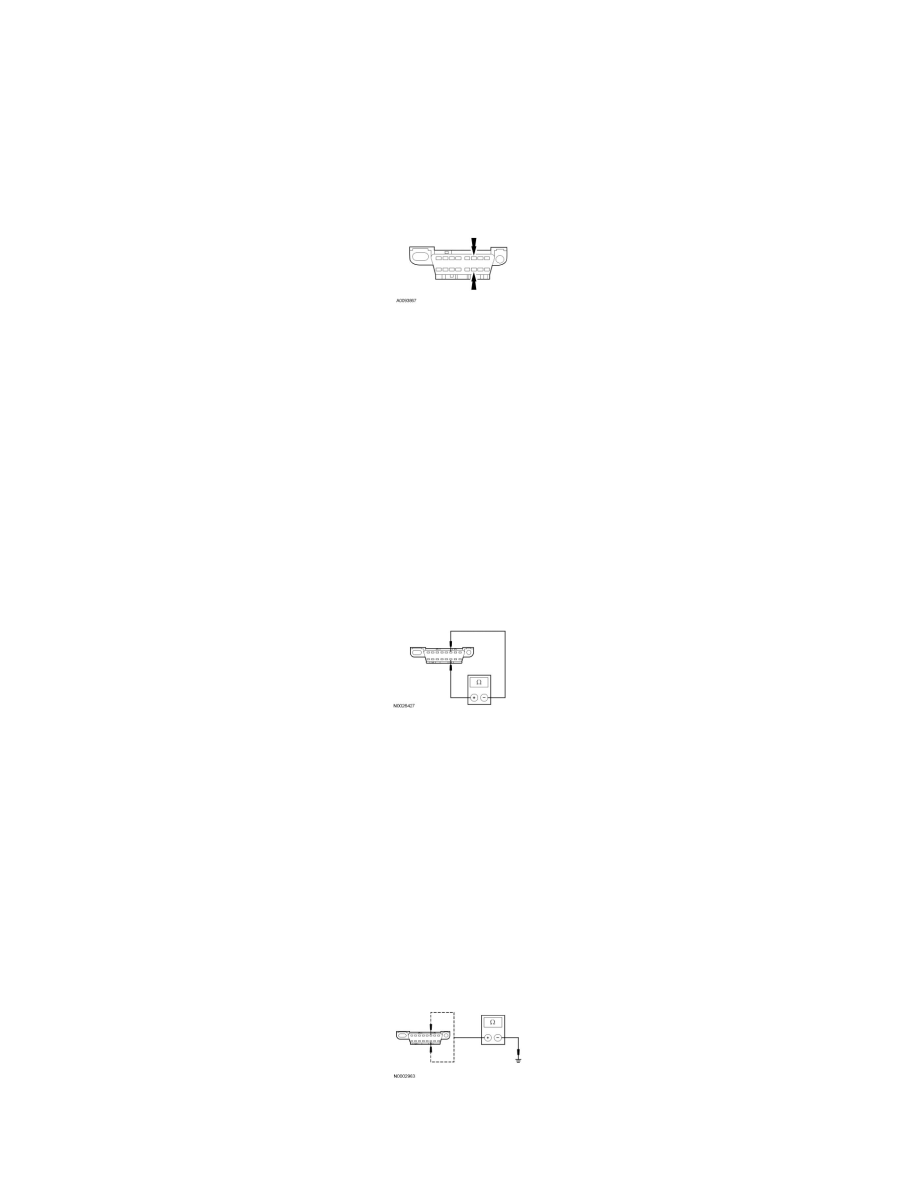
Inspect DLC pins 6 and 14 for damage.
-
Are DLC pins 6 and 14 OK?
Yes
GO to X2.
No
REPAIR the DLC as necessary. CLEAR the DTCs. REPEAT the network test with the scan tool.
-------------------------------------------------
X2 CHECK THE HS-CAN TERMINATION RESISTANCE
-
Ignition OFF.
-
Disconnect: Negative Battery Cable.
-
Measure the resistance between the DLC C251-6, circuit VDB04 (WH/BU), harness side and the DLC C251-14, circuit VDB05 (WH), harness
side.
-
Is the resistance between 54 and 66 ohms?
Yes
GO to X3.
No
GO to X5.
-------------------------------------------------
X3 CHECK THE HS-CAN (+) AND HS-CAN (-) CIRCUITS FOR A SHORT TO GROUND
-
Measure the resistance between the DLC C251-6, circuit VDB04 (WH/BU), harness side and ground; and between the DLC C251-14, circuit
VDB05 (WH), harness side and ground.
-
Are the resistances greater than 1,000 ohms?
Yes