
Expedition 2WD V8-5.4L (2009)
CONNECT the negative battery cable. GO to X28.
-------------------------------------------------
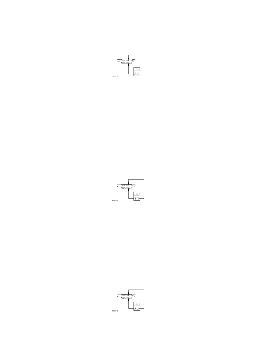
X13 CHECK THE HS-CAN (+) AND HS-CAN (-) CIRCUITS FOR A SHORT TOGETHER WITH THE ABS MODULE DISCONNECTED
-
Disconnect: ABS Module C135.
-
Measure the resistance between the DLC C251-6, circuit VDB04 (WH/BU), harness side and the DLC C251-14, circuit VDB05 (WH), harness
side.
-
Is the resistance less than 5 ohms?
Yes
If the vehicle is equipped with a 4X4 control module, GO to X14.
If the vehicle is not equipped with a 4X4 control module, GO to X15.
No
CONNECT the negative battery cable. GO to X29.
-------------------------------------------------
X14 CHECK THE HS-CAN (+) AND HS-CAN (-) CIRCUITS FOR A SHORT TOGETHER WITH THE 4X4 CONTROL MODULE
DISCONNECTED
-
Disconnect: 4X4 Control Module C281a.
-
Measure the resistance between the DLC C251-6, circuit VDB04 (WH/BU), harness side and the DLC C251-14, circuit VDB05 (WH), harness
side.
-
Is the resistance less than 5 ohms?
Yes
GO to X15.
No
CONNECT the negative battery cable. GO to X30.
-------------------------------------------------
X15 CHECK THE HS-CAN (+) AND HS-CAN (-) CIRCUITS FOR A SHORT TOGETHER WITH THE RCM DISCONNECTED
-
Disconnect: RCM C310b.
-
Measure the resistance between the DLC C251-6, circuit VDB04 (WH/BU), harness side and the DLC C251-14, circuit VDB05 (WH), harness
side.
-
Is the resistance less than 5 ohms?