
Expedition 2WD V8-5.4L (2009)
6. Using the Mastertech(R) Series MTS 4000 Driveline Balance and NVH Analyzer (Vetronix), run a second test with the 12 mm (0.47 in) test
weight set screw in the No. 1 hole, previously marked on the pinion flange.
7. Remove the test weight, then install the weight combination directed by the Mastertech(R) Series MTS 4000 Driveline Balance and NVH
Analyzer (Vetronix).
Vehicles without tapped pinion flanges
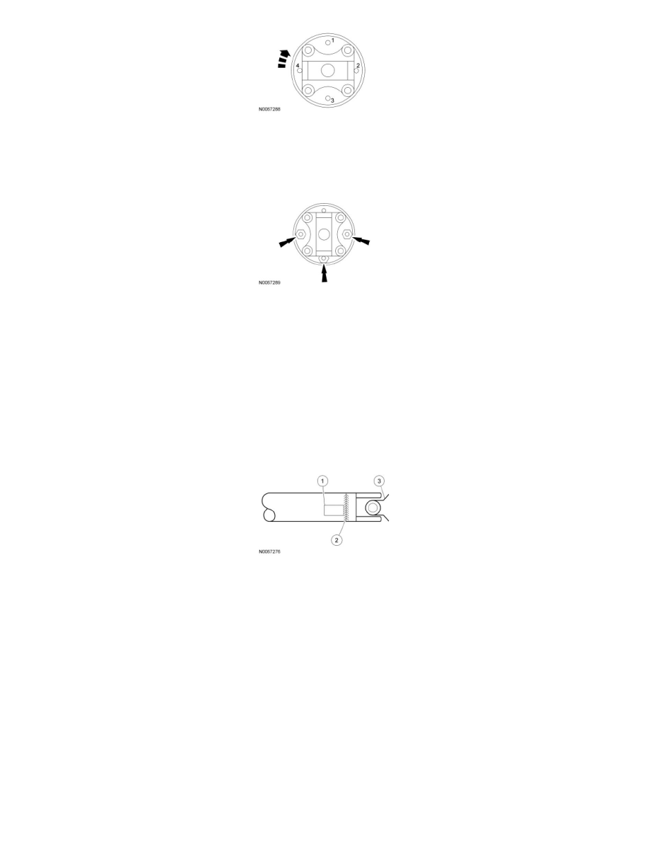
8. Using the Mastertech(R) Series MTS 4000 Driveline Balance and NVH Analyzer (Vetronix), run a second test with a test weight. Using a metal
band, secure the test weight to the end of the driveshaft. The weight should be placed at the end of the driveshaft tube, as close to the tube-to-yoke
weld seam as possible. Mark the location of the test weight on the driveshaft, as shown in the figure below.
1. Test weight.
2. Tube-to-yoke weld seam.
3. Driveshaft pinion flange.
-
Select the test weight based on driveshaft size. Larger driveshafts use 10 g (0.353 oz). Smaller driveshafts use 5 g (0.176 oz).
9. Remove the test weight, then install the recommended weight at the position directed by the Mastertech(R) Series MTS 4000 Driveline Balance
and NVH Analyzer (Vetronix). Using a metal band and epoxy, secure the test weight to the driveshaft, as shown in the figure below.
1. Test weight.
2. Measure in this direction.
3. Driveshaft diameter.
4. Directional rotation.
5. Balance weight relative to test weight centerline.
-
The results are displayed with respect to the location to where the test weight was placed.