
Expedition 4WD V8-5.4L VIN 5 (2006)
Ball Joint: Testing and Inspection
Ball Joint Inspection
1. Prior to inspecting the ball joints for wear, inspect the wheel bearings.
2. WARNING: The electrical power to the air suspension system must be shut off prior to hoisting, jacking or towing an air suspension
vehicle. This can be accomplished by turning off the air suspension switch. Failure to do so can result in unexpected inflation or deflation
of the air springs, which can result in shifting of the vehicle during these operations. Failure to follow these instructions may result in
personal injury.
NOTE: In order to obtain accurate measurements, the suspension must be in full rebound with the weight of the vehicle supported by the frame.
Raise and support the vehicle by the frame to allow the wheels to hang in the rebound position.
3. Inspect the ball joint and ball joint boot for damage.
^
If the ball joint or ball joint boot is damaged, install a new ball joint as necessary.
NOTE: Carry out Steps 4-6 to inspect the lower ball joint. Carry out Steps 7-9 to inspect the upper ball joint.
4. CAUTION: Do not use any tools or equipment to move the wheel and tire assembly or suspension components while checking for relative
movement. Suspension damage can occur. The use of tools or equipment will also create relative movement that may not exist when using hand
force.
Relative movement must be measured using hand force only.
NOTE: The weight of the wheel and tire assembly must be overcome to obtain an accurate measurement on the dial indicator.
Inspect the ball joint for relative movement by alternately pulling downward and pushing upward on the wheel and tire assembly by hand. Note
any relative vertical movement between the wheel knuckle and lower arm at the lower ball joint.
^
If relative movement is not felt or seen, the ball joint is OK. Do not install a new ball joint.
^
If relative movement is found, continue with Step 5.
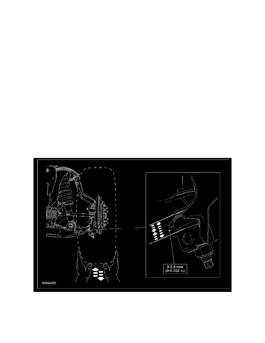
5. NOTE: In order to obtain an accurate measurement, the dial indicator should be aligned as close as possible with the vertical axis (center line) of
the ball joint.
To measure ball joint deflection, attach a suitable dial indicator with a flexible arm between the lower control arm and the wheel knuckle or ball
joint stud.
6. Measure the ball joint deflection while an assistant pushes up and pulls down on the wheel and tire assembly, by hand.
^
If the deflection exceeds the specification, a new ball joint must be installed.