
Explorer 2WD V6-245 4.0L VIN X SFI (1999)
Intake Manifold Runner Control (IMRC) - Electric Actuated
Intake Manifold Runner Control (IMRC) Electric Actuated System
The Intake Manifold Runner Control Electric Actuated system consists of a remote mounted motorized actuator with an attaching cable for each housing
on each bank. Some applications will use one cable for both banks. The cable of linkage attaches to the housing butterfly plate levers. The Escort/Tracer
2.0L (2V) IMRC uses a motorized actuator mounted directly to a single housing without the use of a cable. Each IMRC housing is an aluminum casting
with two intake air passages for each cylinder. One passage is always open and the other is opened and closed with a butterfly valve plate. The housing
uses a return spring to hold the butterfly valve plates closed. The motorized actuator houses an internal switch or switches, depending on the application,
to provide feedback to the PCM indicating cable and butterfly valve plate position.
Below approximately 3000 rpm, the motorized actuator will not be energized. This will allow the cable to fully extend and the butterfly valve plates to
remain closed. Above approximately 3000 rpm, the motorized actuator will be energized. The attaching cable will pull the butterfly valve plates into the
open position. Some vehicles will activate the IMRC near 1500 rpm.
WARNING: SUBSTANTIAL OPENING AND CLOSING TORQUE IS APPLIED BY THIS SYSTEM. TO PREVENT INJURY, BE
CAREFUL TO KEEP FINGERS AWAY FROM LEVER MECHANISMS WHEN ACTUATED.
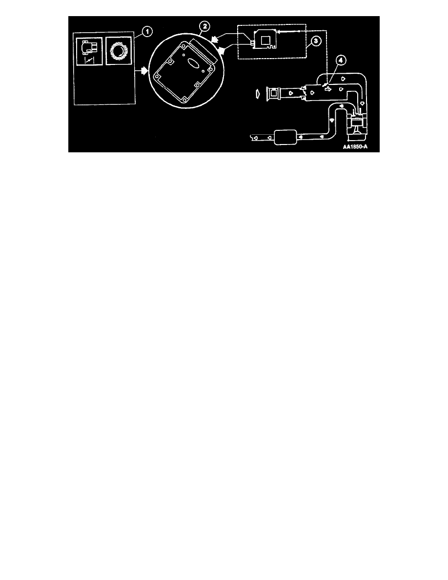
1. The PCM uses the TP sensor and CKP signals to determine activation of the IMRC system. There must be a positive change in voltage from the
TP sensor along with the increase in rpm to open the valve plates.
2. The PCM uses the information from the input signals to control the IMRC motorized actuator based upon rpm and changes in throttle position.
3. The PCM energizes the actuator to pull the butterfly plates open with the cable(s) or linkage.
4. The IMRC housing contain butterfly plates to allow increased air flow.
Intake Manifold Tuning (IMT) Valve
The intake manifold tuning valve is a motorized actuated unit mounted directly to the intake manifold. The IMT valve actuator controls a shutter device
attached to the actuator shaft. There is no monitor input to the PCM with this system to indicate shutter position.
The IMT valve motorized unit will not be energized below approximately 2600 rpm. The shutter will be in the closed position not allowing airflow
blend to occur in the intake manifold. Above approximately 2600 rpm, the motorized unit will be energized. The motorized unit will be commanded on
by the PCM initially at a 100 percent duty cycle to move the shutter to the open position and then falling to approximately 50 percent to continue to hold
the shutter open.
1. The PCM uses the TP sensor and CKP signals to determine activation of the IMT valve system. There must be a positive change in voltage from
the TP sensor along with the increase in rpm to open the shutter.
2. The PCM uses the information from the input signals to control the IMT valve.
3. When commanded on by the PCM, the motorized actuator shutter opens up the end of the vertical separating wall at high engine speeds to allow
both sides of the manifold to blend together.
Throttle Body System Overview
The throttle body system meters air to the engine during idle, part throttle, and Wide Open Throttle (WOT) conditions. The throttle body system consists
of an Idle Air Control (IAC) valve assembly, idle air orifice, single or dual bores with butterfly valve throttle plates and a Throttle Position (TP) sensor.
One other source of idle air flow is the Positive Crankcase Ventilation (PCV) system. The combined idle air flow (from idle air orifice IAC flow and
PCV flow) is measured by the MAF sensor on all applications.
During idle, the throttle body assembly provides a set amount of air flow to the engine through the idle air passage and PCV valve. The IAC valve
assembly provides additional air when commanded by the Powertrain Control Module (PCM) to maintain the proper engine idle speed under varying