
Explorer 2WD V6-4.0L VIN K (2007)
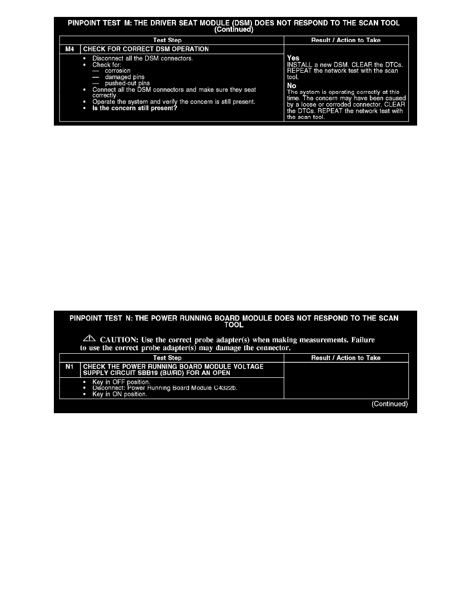
M4
Normal Operation
The DSM communicates with the scan tool through the medium speed controller area network (MS-CAN). Circuits VDB06 (GY/OG) (MS-CAN +)
and VDB07 (VT/OG) (MS-CAN -) provide the network connection to the DSM. The DSM shares the MS-CAN network with the instrument cluster,
the smart junction box (SJB), the electronic automatic temperature control (EATC) module (if equipped), the audio unit, the digital versatile disc
(DVD) player (if equipped), the satellite radio receiver (if equipped), the power running board module (if equipped) and the parking aid module (if
equipped). Voltage for the DSM is provided by circuit SBP01 (RD). Circuit GD143 (BK/OG) provides ground.
Possible Causes
-
Fuse
-
Circuit GD143 (BK/OG) open
-
Circuit SBP01 (RD) open
-
Circuit VDB06 (GY/OG) open (MS-CAN +)
-
Circuit VDB07 (VT/OG) open (MS-CAN -)
-
DSM
Test N: The Power Running Board Module Does Not Respond to the Scan Tool
PINPOINT TEST N: THE POWER RUNNING BOARD MODULE DOES NOT RESPOND TO THE SCAN TOOL
N1