
Explorer 2WD V8-4.6L VIN 8 (2006)
Removal
WARNING: Do not smoke or carry lighted tobacco or open flame of any type when working on or near any fuel-related component. Highly
flammable mixtures are always present and may be ignited. Failure to follow these instructions may result in personal injury.
WARNING: Fuel in the fuel system remains under high pressure even when the engine is not running. Before servicing or disconnecting any
of the fuel lines or fuel system components, the fuel system pressure must be relieved to prevent accidental spraying of fuel, causing a fire
hazard. Failure to follow these instructions may result in personal injury.
1. Remove the air cleaner outlet pipe.
2. Remove the fuel rail and injectors.
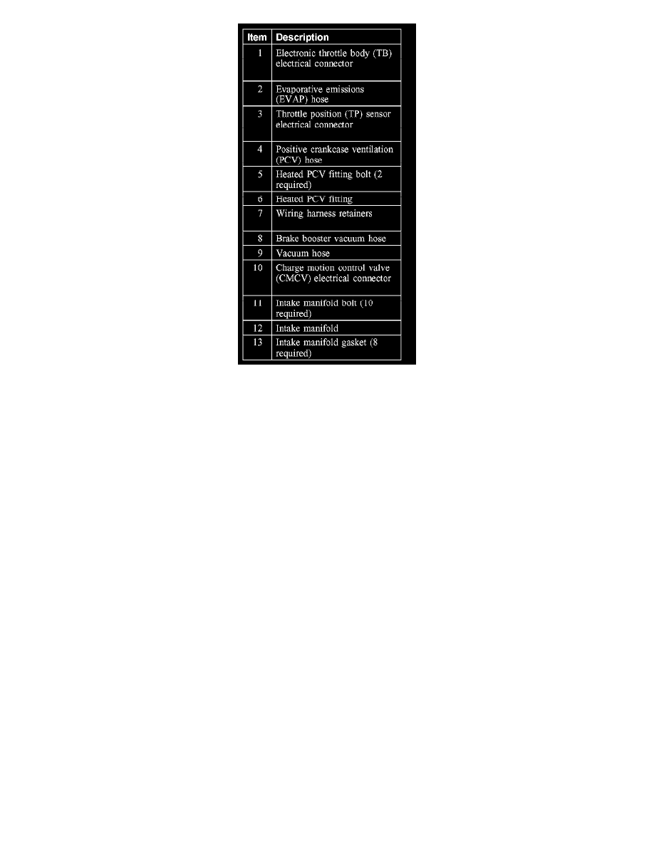
3. Disconnect the electronic throttle body (TB) electrical connector.
4. Disconnect the evaporative emissions (EVAP) tube from the intake manifold.
5. Disconnect the throttle position (TP) sensor electrical connector.
6. Disconnect the positive crankcase ventilation (PCV) hose from the heated PCV fitting on the intake manifold.
7. Remove the bolts and position the heated PCV fitting aside.
^
Remove and discard the O-ring seal.
8. Detach the wiring harness retainers from the intake manifold.
9. Disconnect the brake booster vacuum hose from the rear of the intake manifold.
10. Disconnect the vacuum hose from the rear of the intake manifold.
11. Disconnect the charge motion control valve (CMCV) electrical connector.
12. Remove the bolts, the intake manifold and the gaskets.
^
Discard the gaskets.
Installation
1. CAUTION: Do not use metal scrapers, wire brushes, power abrasive discs or other abrasive means to clean the sealing surfaces. These tools
cause scratches and gouges which make leak paths. Use a plastic scraping tool to remove all traces of old gaskets.
NOTE: Clean and inspect the sealing surfaces with metal surface prep. Follow the directions on the packaging.
NOTE: Electrical and vacuum harnesses must not restrict movement of the CMCV control rods at the rear of the intake manifold. Use extreme
care during the installation of the intake manifold to prevent any pinching of electrical and vacuum harnesses.
Using new intake manifold gaskets, position the intake manifold.