
Explorer Sport 4WD V6-245 4.0L SOHC VIN K SFI (2001)
STRIKERS, SEATS AND HOOD LATCHES.
^
PLEASE REFER TO THE APPROPRIATE COMPONENT OR SYSTEM TO DETERMINE LOCATION OF THE FRONT AIR BAG
SENSORS.
^
THE SIDE AIR BAG SENSORS ARE LOCATED AT OR NEAR THE BASE OF THE B-PILLAR.
^
TO DEPLETE THE BACKUP POWER SUPPLY ENERGY, DISCONNECT THE BATTERY GROUND CABLE AND WAIT AT LEAST
ONE MINUTE. BE SURE TO DISCONNECT AUXILIARY BATTERIES AND POWER SUPPLIES (IF EQUIPPED).
^
THE RESTRAINT SYSTEM DIAGNOSTIC TOOL IS FOR RESTRAINT SYSTEM SERVICE ONLY. REMOVE FROM VEHICLE
PRIOR TO ROAD USE. FAILURE TO REMOVE COULD RESULT IN INJURY AND POSSIBLE VIOLATION OF VEHICLE SAFETY
STANDARDS.
NOTE:
^
If a seat equipped with a seat mounted side airbag system is being serviced the airbag system must be deactivated using the appropriate
deactivation procedure.
^
Restraint system diagnostic tools MUST be installed under the seats in the side airbag floor connectors.
^
Diagnostics or repairs are not to be performed on a side airbag system with the seats in the vehicle. Prior to attempting to diagnose/repair the
side airbag system, the seats must be removed from the vehicle and the restraint system diagnostic tools must be installed in the side airbag
floor connectors. The restraint system diagnostic tools must be removed prior to operating the vehicle over the road.
^
Diagnostics may be performed on systems other than the side airbag system (lumbar, climate controlled, heated, power seat track) with the seat
installed in the vehicle as long as the restraint system diagnostic tools are installed under the seats in the side airbag floor connectors.
^
After diagnosing/repairing a seat system the restraint system diagnostic tools must be removed before operating the vehicle over the road.
3. Wait at least one minute for the backup power supply in the Restraints Control Module (RCM) to deplete its stored energy.
4. Access the driver air bag electrical connector to the clockspring behind the lower steering column opening finish panel.
5. Disconnect the driver air bag electrical connector to the clockspring.
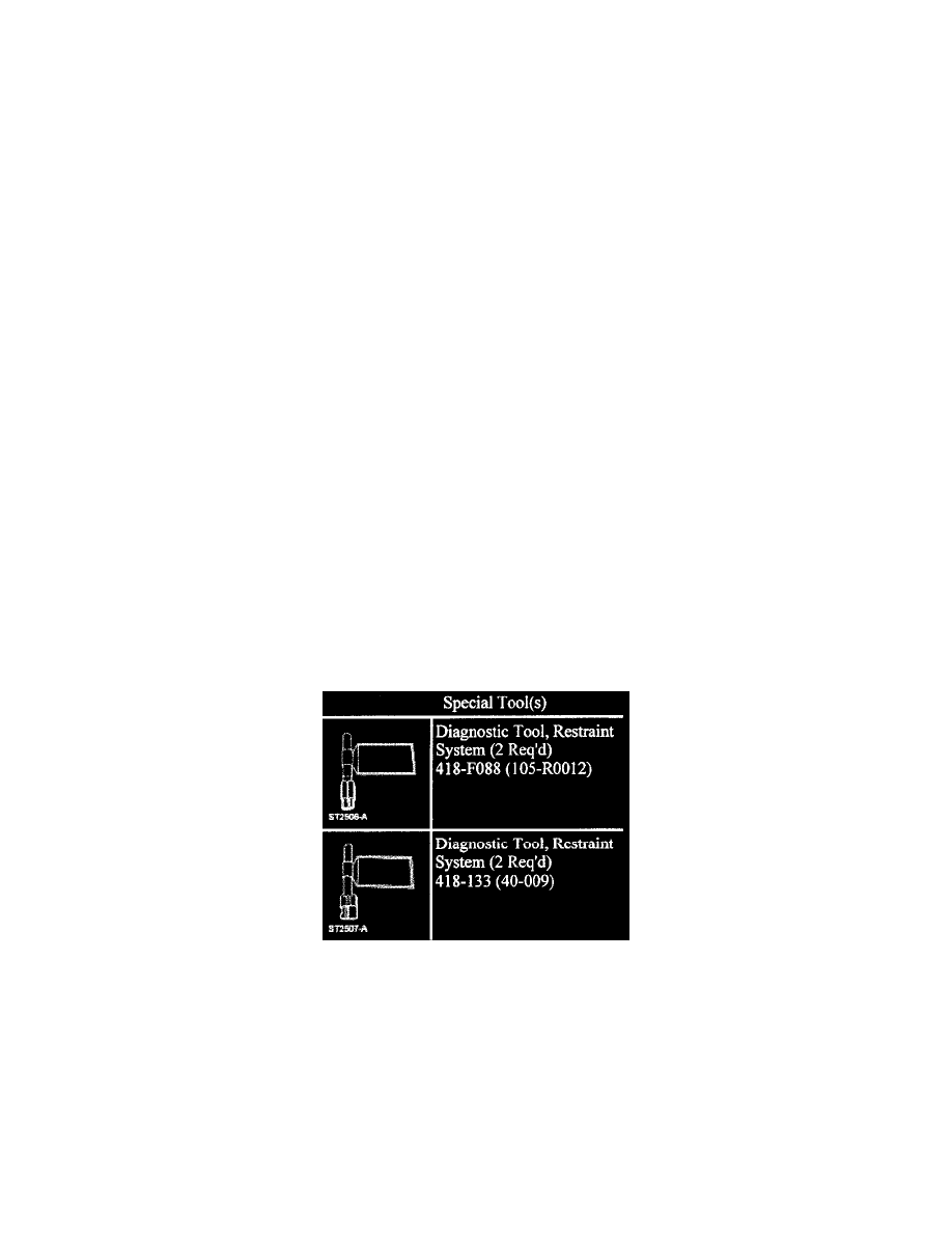
6. Attach a restraint system diagnostic tool 418-F088 (105-R0012) to the vehicle harness side of the clockspring connector.
7. Disconnect the passenger air bag.
8. Attach a restraint system diagnostic tool 418-F088 (105-R0012) to the harness side of the passenger air bag connector.
9. If equipped with side air bags, disconnect the passenger side air bag connector beneath the front seat.
10. If equipped with side air bags, attach a restraint system diagnostic tool 418-133 (40-009) to the passenger side air bag electrical connector beneath
the front seat.
11. If equipped with side air bags, disconnect the side air bag connector beneath the driver seat.
12. If equipped with side air bags, attach a restraint system diagnostic tool 418-133 (40-009) to the driver side air bag electrical connector beneath the
front seat.
13. Reconnect the battery ground cable.
Deactivation Procedure
Supplemental Restraint System (SRS) Deactivation and Reactivation Deactivation
WARNING: Always wear safety glasses when repairing an air bag supplemental restraint system (SRS) vehicle and when handling an air
bag module. This will reduce the risk of injury in the event of an accidental deployment.
WARNING: Carry a live air bag module with the air bag and trim cover pointed away from your body. This will reduce the risk of injury in
the event of an accidental deployment.
WARNING: Do not set a live air bag module down with the trim cover face down. This will This will reduce the risk of injury in the event of
an accidental deployment.
WARNING: To reduce the risk of personal injury, do not use any memory saver devices.