
F 100 2WD Pickup L6-300 4.9L (1983)
MCU: Customer Interest
Engine - Spark Knock/Detonation
Article No. 83-6-26
SPARK KNOCK/DETONATION - 4.9L/ 5.0L/5.8L(W) - ALL 1983 LIGHT TRUCKS OVER OR UNDER 8500 LB. GVW
LIGHT TRUCKS 1983 F SERIES AND ECONOLINE
CALIBRATIONS: All 1983 4.9L/5.0L/5.8L(W) used in Light Trucks
If one of the above-mentioned engines experiences spark knock/detonation, the procedure listed below may be applied to minimize the concern.
1.
Check the integrity of the engine emission components by ensuring that the vacuum hose system is not leaking and that all the vacuum hose
connections have been properly made.
2.
Check the EGR valve as described in the 1983 Engine/Emissions Diagnosis Manual, to determine if it is functioning properly.
3.
For Dura-Spark Ignition Equipped Vehicles & MCU Equipped Vehicles
a.
Verify that the engine initial timing is set to the decal specification.
b.
If, after verifying the correct initial timing, the detonation still persists, retard the initial timing in 2~ increments, to a maximum 6~ until the
condition is resolved.
NOTE:
A trace of detonation during heavy road loads is acceptable.
c.
Check, and reset if necessary, the engine idle speed.
4.
For EEF III Equipped Vehicles
EEC III equipped vehicles can easily be identified by the lack of either centrifugal or vacuum advance mechanisms on the distributor.
a.
Perform the EEC functional self-test check to verify proper functioning of the system. Refer to the 1983 Car/Truck Engine/Emissions
Diagnosis Manual.
b.
Locate the EEC processor assembly and remove the calibration assembly. On the "F" series, it is under the driver's seat and it is necessary to
remove the processor assembly to remove the calibration assembly. On the "E" series, the processor assembly is located underneath the dash
panel on the passenger side.
c.
Remove the warranty tag on the calibration assembly and place the switch in the #1 (3~ retard) or #2 (6~ retard) position as required to
resolve the condition.
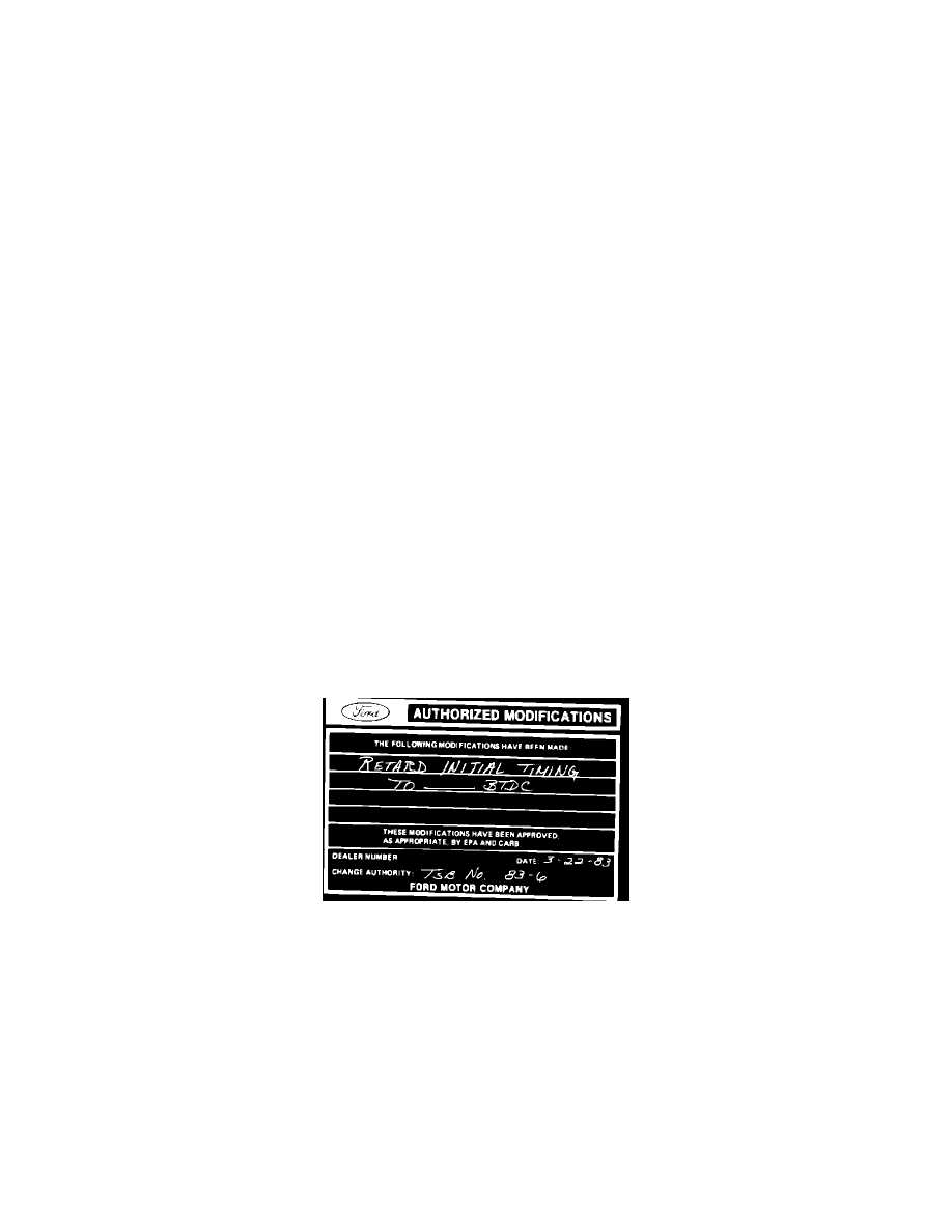
Obtain an Authorized Modifications decal and list the date, dealer number and summary of alterations performed. Select a prominent place adjacent to
the Vehicle Emission Control Information decal suitable for installing the Authorized Modifications decal. Clean the area, install the decal and cover it
with a clear plastic decal shield.
OTHER APPLICABLE ARTICLES: None
WARRANTY STATUS: Reimbursable within the provisions of the Warranty and Policy Manual.
OPERATION/TIME: "Actual Time" as defined in the Warranty and Policy Manual.
DLR. CODING: Basic Part No. DRIVE Code: H9