
F 100 2WD Pickup V8-400 6.6L (1982)
Intake Manifold: Service and Repair
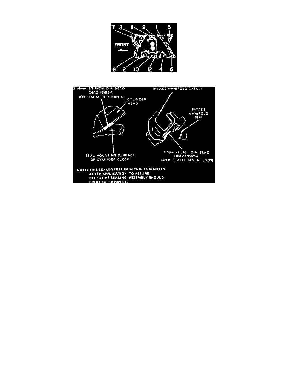
Fig. 14 Intake manifold tightening sequence. V8-351M & 400
Fig. 20 Intake manifold installation. V8 engines
V8-351M & 400
1.
Remove air cleaner and intake duct.
2.
On models equipped with A/C, isolate and remove A/C compressor.
3.
On all models, disconnect high tension lead and wires from ignition coil.
4.
Disconnect ignition wires from spark plugs, then remove wires from brackets on rocker arm covers.
5.
Remove distributor cap and ignition wires as an assembly.
6.
Remove Thermactor bypass valve and hose from check valve.
7.
Disconnect fuel inlet line from carburetor.
8.
Disconnect heater hoses from retainers and position aside.
9.
Remove ignition coil, vacuum solenoid valve and bracket, then disconnect crankcase emission hose from left rocker arm cover.
10.
Disconnect vacuum lines from intake manifold and distributor.
11.
Remove distributor hold-down bolt and the distributor.
12.
Disconnect accelerator linkage and speed control cable (if equipped) from carburetor assembly.
13.
On models equipped with automatic transmission, disconnect transmission downshift linkage.
14.
On all models, remove carburetor or throttle body, then the manifold attaching bolts and manifold.
15.
Remove and discard manifold valley baffle and seals.
16.
Reverse procedure to install. Apply sealer as shown in Fig. 20. Torque manifold attaching bolts to 22-32 ft-lbs for 3/8" bolts, or 19-25 ft-lbs for
5/16" bolts in sequence as shown in Fig. 14.