F 150 2WD V8-4.6L (2008)

Connecting Rod: Specifications
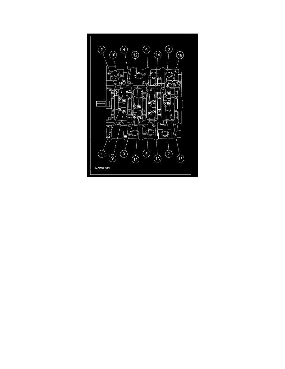
Connecting Rod Cap Bolts
Discard the bolts.
First pass ................................................................................................................................................................................................. 43 Nm (32 lb-ft).
Final pass ................................................................................................................................................................................. Tighten an additional 105°
Connecting Rod
Clearance-to-pin .................................................................................................................................................... 0.015-0.040 mm (0.0006-0.0016 inch)
Pin bore diameter .................................................................................................................................................. 21.959-21.979 mm (0.864-0.865 inch)
Length (center-to-center) ................................................................................................................................................................. 150.7 mm (5.93 inch)
Maximum allowed bend .................................................................................................................................. 0.038 mm per 25 mm (0.0015-0.984 inch)
Maximum allowed twist (a) ............................................................................................................................. 0.050 mm per 25 mm (0.0015-0.984 inch)
Bearing bore diameter ............................................................................................................................................. 56.756-56.876 mm (2.234-2.24 inch)
Bearing-to-crankshaft clearance .............................................................................................................................. 0.027-0.069 mm (0.001-0.0027 inch)
Side clearance (assembled to crank)
Standard ............................................................................................................................................................ 0.015-0.45 mm (0.0006-0.0177 inch)
Service limit ...................................................................................................................................................................... 0.05 mm (0.002 inch) max.
(a) The pin bore and crank bearing bore must be parallel and in the same vertical plane within the specified total difference when measured at the ends
of a 203 mm bar, 105.5 mm on each side of rod centerline.
