
F 150 2WD Pickup V8-5.4L SOHC VIN 5 (2004)
6. Attach the restraint system diagnostic tool to the vehicle harness side of the clockspring electrical connector.
7. Connect the battery ground cable.
8. With the restraint system diagnostic tools installed at all deployable devices, prove out the supplemental restraint system (SRS). See: Air Bag(s)
Arming and Disarming/Service and Repair/Prove Out Procedure
9. Disconnect the battery ground cable and wait at least one minute.
Item 5: Tape Removal Note
1. If installing the same clockspring, apply two strips of masking tape across the clockspring to prevent accidental rotation when the clockspring is
removed.
Item 7: Multi-function Switch Removal Note
1. While releasing the retaining tab at the top of the multi-function switch, slide the multi-function switch up and out of the way.
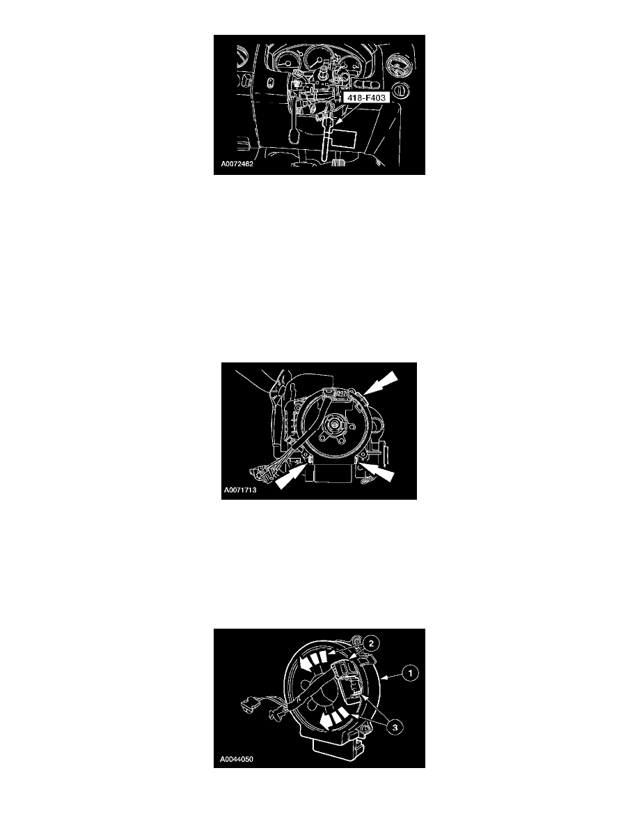
Item 9: Clockspring Removal Note
1. Release the three clips and remove the clockspring.
Item 11: Clockspring Mounting Bracket Removal Note
1. Inspect the clockspring mounting bracket for damage and remove as necessary.
INSTALLATION
WARNING: To reduce the risk of serious personal injury, read and follow all warnings, cautions and notes at the beginning of the removal
procedure.
1. WARNING: Incorrect centralization may result in premature component failure. If in doubt when centralizing the clockspring, repeat