
F 150 2WD Pickup V8-5.4L SOHC VIN 5 (2004)
to remove could result in injury and possible violation of vehicle safety standards.
With all the restraint system diagnostic tools removed, prove out the supplemental restraint system (SRS). See: Body and Frame/Interior
Moulding / Trim/Dashboard / Instrument Panel/Air Bag(s) Arming and Disarming/Service and Repair/Prove Out Procedure
21. Check the active restraint system for correct operation.
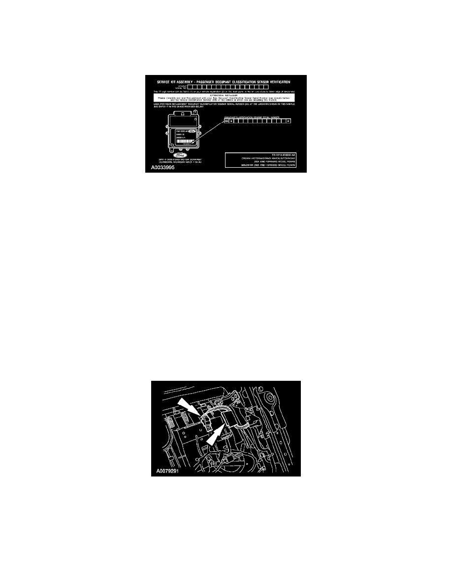
22. NOTE: When installing a new occupant classification sensor, a prepaid return postcard is provided with the new occupant classification sensor.
The serial number for the new part and the vehicle identification number (VIN) must be recorded and sent to Ford Motor Company.
Fill out the necessary information on the occupant classification sensor traceability card and return it along with the complete inoperative occupant
classification sensor to Ford Motor Company.
-
When returning the inoperative occupant classification sensor, include the following: seat cushion foam pad, bladder, electronic control unit,
pressure sensor (transducer), hose, electrical connectors and wire harness (service part occupant classification sensor only).
Item 1: Seat Cushion Assembly Installation Note
1. Make sure the trim cover J-clips left unattached for purposes of routing the belt tension sensor wire harness or lumbar cable are accessible after the
seat cushion assembly has been positioned to the seat track.
2. Position the safety belt buckle through the seat cushion strap.
Item 3: Electrical Connector Installation Note
1. If equipped, connect the backrest heated seat element electrical connector and attach any wire harness retainers to the seat cushion pan.
2. If equipped, connect the power seat switch electrical connector.
3. If equipped, connect the power seat motor electrical connector and attach any wire harness retainers to the seat cushion pan.
4. NOTE: If equipped with manual lumbar, make sure this wire harness is routed above the manual lumbar cable.
Connect the safety belt buckle pretensioner and safety belt buckle switch electrical connectors and attach the wire harness retainer to the seat track.
Item 4: Belt Tension Sensor Electrical Connector (Vehicles With Seat Integrated Restraints Only) Installation Note
1. Route the wire harness, connect the electrical connector and attach the J-clip.
Item 5: Lumbar Cable Installation Note