
F 150 4WD V8-4.6L VIN 8 (2010)
-
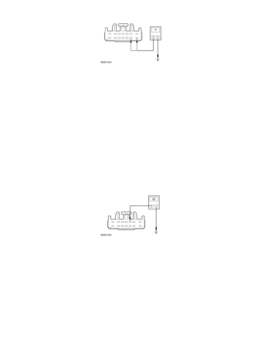
TBC module C2142-9, circuit CBP33 (WH/BN), harness side.
-
Are the voltages greater than 10 volts?
Yes
GO to D5.
No
VERIFY BJB fuse 17 (30A) is OK. If OK, REPAIR circuit SBB17 (RD).
VERIFY SJB fuse 33 (10A) is OK. If OK, REPAIR circuit CBP33 (WH/BN).
If either fuse is not OK, REFER to the Wiring Diagrams to identify the possible causes of the circuit short. See: Diagrams/Electrical Diagrams/Diagrams
By Number
CLEAR the DTCs. REPEAT the self-test.
-------------------------------------------------
D5 CHECK THE TBC MODULE GROUND CIRCUIT FOR AN OPEN
-
Ignition OFF.
-
Measure the resistance between TBC module C2142-3, circuit GD138 (BK/WH), harness side and ground.
-
Is the resistance less than 5 ohms?
Yes
GO to D6.
No
REPAIR circuit GD138 (BK/WH). CLEAR the DTCs. REPEAT the self-test.
-------------------------------------------------
D6 CHECK THE TBC MODULE PWM OUTPUT CIRCUIT FOR AN OPEN
-
Measure the resistance between trailer tow 7-pin trailer tow connector pin-3, circuit CAT19 (BU), harness side and TBC module C2142-14, circuit
CAT19 (BU), harness side.