
F 150 4WD V8-4.6L VIN 8 (2010)
Information Bus: Initial Inspection and Diagnostic Overview
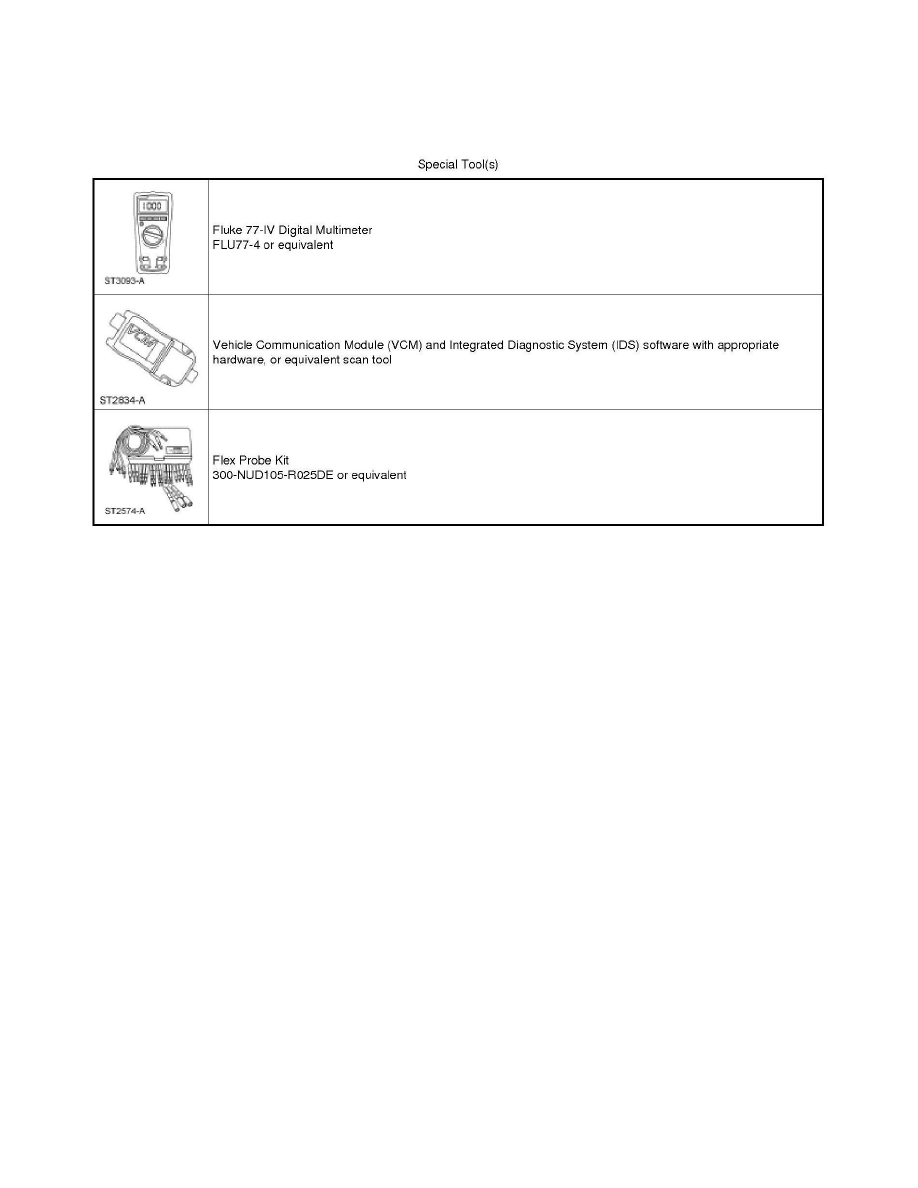
Special Tools Used With Diagnostics
Communications Network
Principles of Operation
Communications Network
Principles of Operation
NOTE: The Smart Junction Box (SJB) is also known as the Generic Electronic Module (GEM).
Both the High Speed Controller Area Network (HS-CAN) and the Medium Speed Controller Area Network (MS-CAN) use an unshielded twisted-pair
cable of data (+) and data (-) circuits. The HS-CAN operates at a maximum data transfer speed of 500 Kbps and is designed for real time information
transfer and control. The MS-CAN operates at a maximum data transfer speed of 125 Kbps for bus messages and is designed for general information
transfer.
Controller Area Network (CAN) Fault Tolerance
NOTE: The oscilloscope traces below are from the Integrated Diagnostic System (IDS) oscilloscope taken using the CAN setup defaults. The traces are
for both data (+) and data (-) taken simultaneously (2-channel) at a sample rate of 1 mega-sample per second (1MS/s) or greater and viewed at 20
microseconds (20µs) per division. Readings taken with a different oscilloscope will vary from those shown. Compare any suspect readings to a known
good vehicle.
Normal CAN Operation