F 150 4WD Pickup V8-302 5.0L VIN F 2-bbl (1985)

Fuel Injector: All Technical Service Bulletins
Fuel Injector - Rough Idle/Stall After Hot Soak
Article No. 85-15-20
IDLE - ROUGH/STALL AFTER HOT SOAK (5.0L WITH EFI)
LIGHT TRUCK 1985 F SERIES, BRONCO
CALIBRATIONS: ALL 5.0L EFI
WARNING:
This modification is authorized only for the listed engines. Performing this modification on other engine calibrations is unauthorized and
could create liability under applicable federal or local laws.
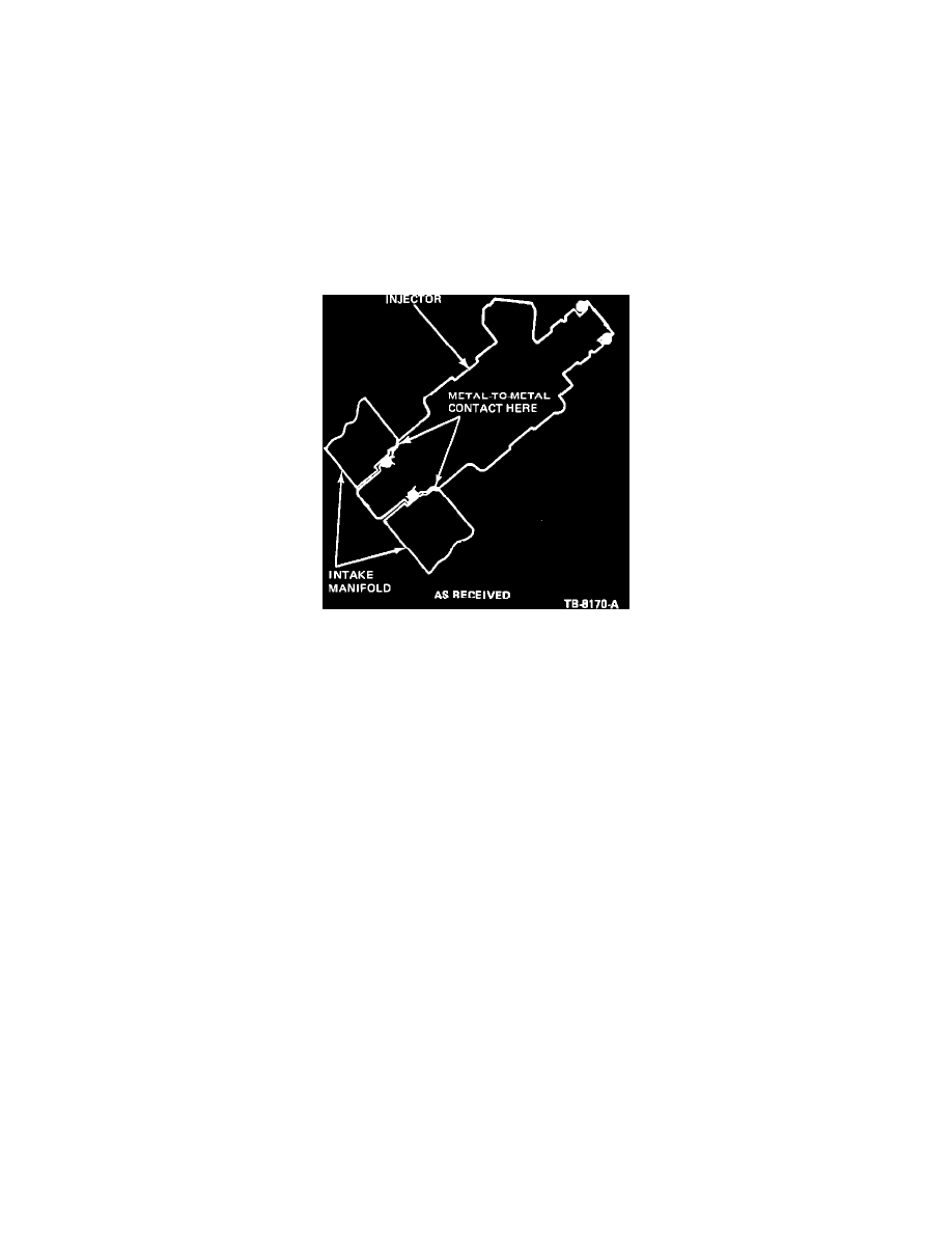
Figure 24 - Injector
After extended hot soak, metal to metal contact between injector and lower intake manifold could cause rough idle/stall at idle conditions, see Figure 24.
Establishing continuity using an ohmmeter as outlined below (or alternately a light bulb continuity check can be used) does not necessarily mean
injector/manifold contact exists. (This is because in some cases contacts may occur between injector and fuel supply manifold which in turn is in contact
with intake manifold.) However, if there is no continuity, it positively rules out that poor idle problem is related to injector contacting intake manifold
and cannot be repaired by following the procedure outlined below.
CAUTION: This service procedure applies only to engines built between Job No. 1 and 5/14/85. Engines built after 5/14/85 have revised injector
pocket machining that is not compatible with actions taken by this TSB. Manifold vacuum and fuel leaks could result if this fix is applied
to an engine built after 5/14/85. Engines built after 5/14/85 are identified with green paint on the intake manifold casting surface directly
above the water outlet. All steps outlined in the Diagnostic Manual for rough idle/engine stall after hot soak must have been exhausted
prior to using this procedure.
Procedure
On a customer concern basis to alleviate the above condition, perform the following:
1.
Read the engine build data from the decal on the rocker arm cover. THIS TSB DOES NOT APPLY IF THE ENGINE WAS BUILT AFTER
5/14/85.
2.
Remove the upper intake manifold using the procedure outlined in Section 24-05 of the 1985 Light Truck Shop Manual.
3.
With an ohmmeter, touch the injector body with one terminal and the lower intake manifold with the other terminal (scratch the respective surfaces
locally to ensure proper contact of the terminal). Infinite resistance shows there is no metal to metal contact between the injector and the intake
manifold. Repeat this check for all eight injectors. Mark those injector locations where continuity was observed. Rework all the injectors in the
bank where at least one injector location was marked. (For example, if there was continuity with one or more injectors in the left bank, and none in
the right bank, all injectors in the left bank only should be reworked.)
4.
Remove retaining screws (two per each fuel supply manifold) and carefully lift injector/fuel supply manifold together from intake manifold until
injector tips clear intake manifold. Be careful not to damage the fuel supply and return line connections.
