
F 250 2WD Pickup V8-351 5.8L (1982)
Engine Control Module: Description and Operation
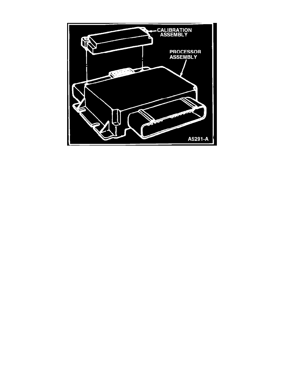
Fig. 7 Processor & calibration assembly
The Electronic Control Assembly (ECA), Fig. 7, is the brain of the system. It is a solid state pre-programmed micro-computer which consists of a
processor assembly and a calibration assembly, Fig. 7.
The processor assembly contains the electronic circuitry which performs the following functions within a fraction of a second:
a.
Choose one of the sensor inputs for evaluation.
b.
Converts the input to a form usable by the computer to use that signal for calculations.
c.
Choose the proper operating strategy necessary for the operating conditions.
d.
Perform spark, EGR, air/fuel ratio, canister purge, throttle kicker and other calculations.
e.
Send electrical output control signals to the ignition module and control solenoids to adjust timing and dwell, EGR flow rate, thermactor air mode
and throttle kicker mode.
The processor assembly also contains a separate power supply which provides a continuous reference voltage of about 9 volts nominal to the sensors.
The calibration assembly, Fig. 7, contains electronic circuitry which provides calibration equations necessary for specific vehicle application for use
by the processor assembly, and provides adjustments for octane problems.
The calibration assembly is mounted on the processor assembly.
The power relay supplies battery voltage to the EEC system and is mounted on the right hand side of the ECA mounting bracket. It also protects the
ECA from possible damage due to reversed polarity.