
F 250 2WD Pickup V8-7.3L DSL Turbo VIN F (1994)
Clockspring Assembly / Spiral Cable: Service and Repair
Removal and Installation
REMOVAL
1. Make sure that vehicle's front wheels are in the straight-ahead position and steering column shaft alignment mark is at the 12 o'clock position.
2. Disconnect battery to starter relay cable for at least one minute to let the air bag backup power supply discharge.
3. Remove steering wheel.
4. Remove lower right and left mouldings from instrument panel by pulling up and out of retainer.
5. Remove instrument panel lower trim panel and steering column shroud.
6. Disconnect air bag sliding contact wire harness.
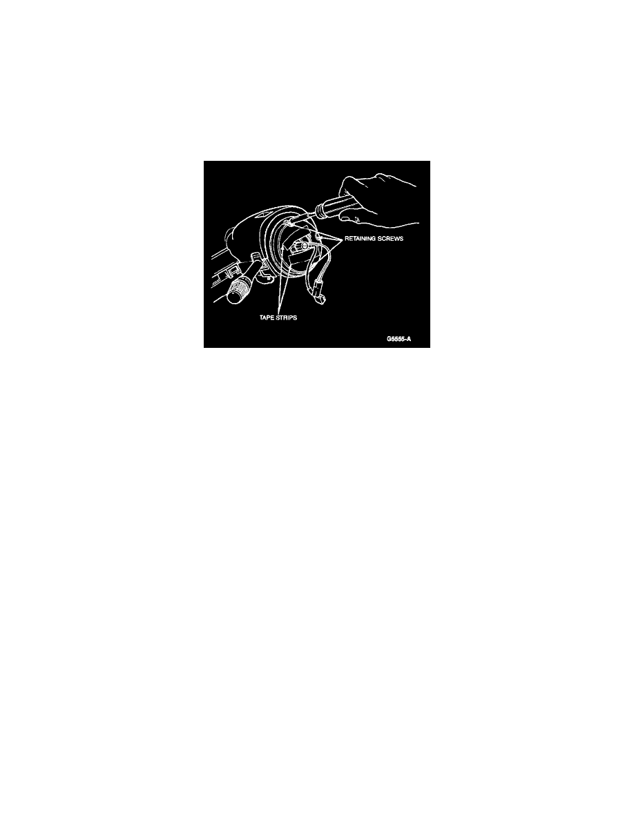
7. Apply two strips of tape across air bag sliding contact stator and rotor to prevent accidental rotation.
8. Remove three screws retaining air bag sliding contact, disconnect from wire harness, and pull air bag sliding contact off steering column shaft.
INSTALLATION
1. Make sure that vehicle's front wheels are in the straight-ahead position and steering column shaft alignment mark is at the 12 o'clock position.
2. Align air bag sliding contact to column shaft and mounting bosses and slide air bag sliding contact onto the shaft.
3. Install three retaining screws. Tighten screws to 2-3 Nm (18-26 in lbs). Remove tape strips.
NOTE: If a new air bag sliding contact is being installed, remove the plastic lock mechanism after air bag sliding contact is secured to column.
4. Route air bag sliding contact wires down steering column shaft and connect to wire harness.
5. Install steering column shroud and instrument cluster mask.
6. Install steering wheel.
7. Connect battery to starter relay cable.
NOTE: When the battery has been disconnected and reconnected, some abnormal drive symptoms may occur while the powertrain control
module relearns its adaptive strategy. The vehicle may need to be driven 10 miles or more to relearn the strategy.