
F 250 2WD Super Duty V10-6.8L (2009)
Cylinder No. 10 front intake valve roller follower
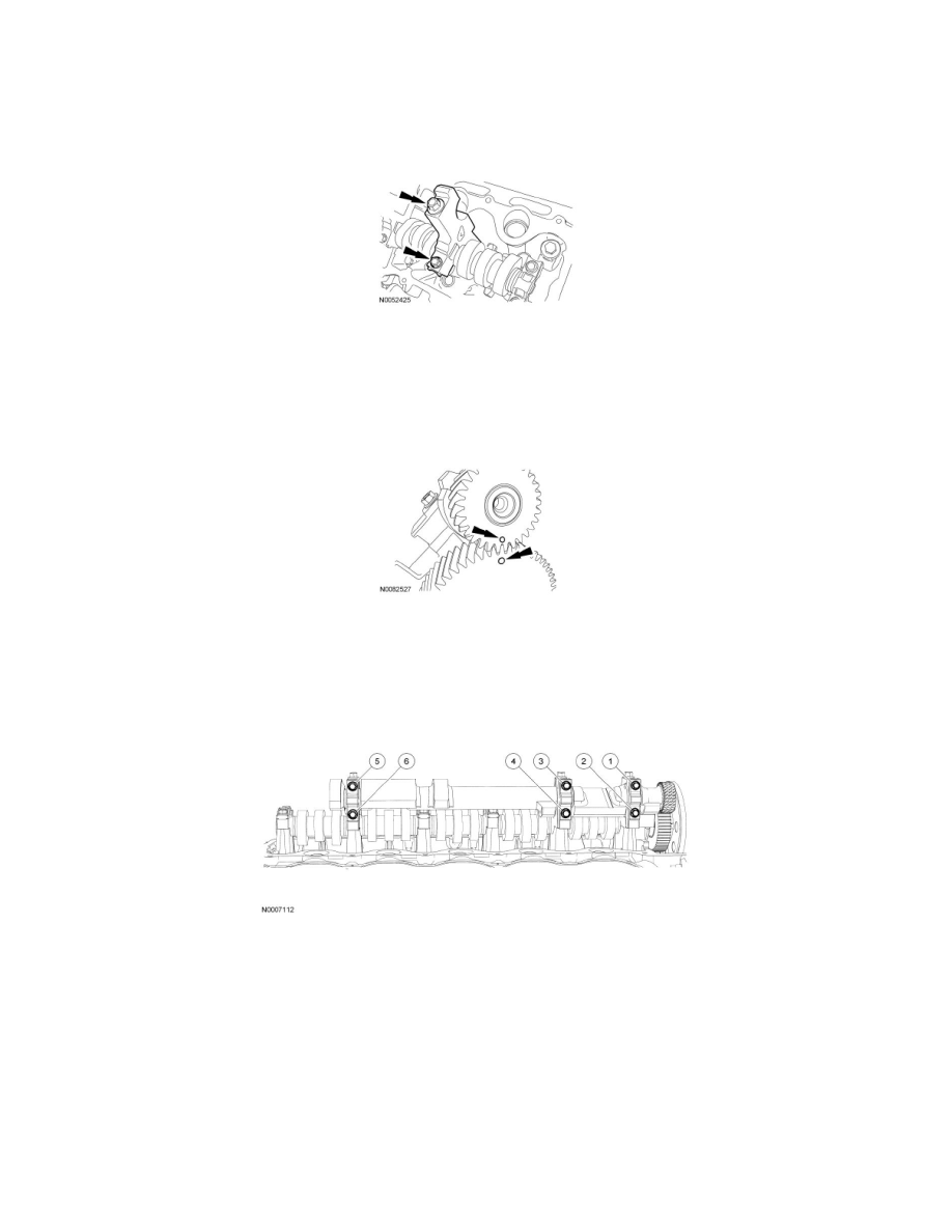
7. Position the camshaft bearing cap and install the 2 bolts in 2 stages:
-
Stage 1: Tighten to 8 Nm (71 lb-in).
-
Stage 2: Tighten an additional 45 degrees.
8. Lubricate the balance shaft journals with clean engine oil.
9. NOTE: Camshaft sprocket removed from art for clarity.
NOTE: It may be necessary to rotate the crankshaft clockwise to align the balance shaft timing marks.
Position the balance shaft on the journals and align the timing mark on the balance shaft with the camshaft timing mark as shown.
10. NOTICE: The balance shaft bearing caps must be installed into their original locations or engine damage may occur.
Position the 3 balance shaft bearing caps and install the 6 bolts and tighten in the sequence shown.
-
Tighten to 10 Nm (89 lb-in).
All camshaft roller followers
11. Depending on the valve being serviced, install the LH or RH valve cover. For additional information, refer to Valve Cover - LH See: Valve
Cover/Service and Repair/Valve Cover - LH or Valve Cover - RH See: Valve Cover/Service and Repair/Valve Cover - RH.