
F 250 2WD Super Duty V10-6.8L (2009)
Alignment: Service and Repair
Camber and Caster Adjustment
Camber and Caster Adjustment - F-250 and F-350 Rear Wheel Drive (RWD)
1. Using alignment equipment and the manufacturer's instructions, measure the caster and camber.
-
Refer to Alignment Specifications in the Specifications for optimal alignment settings.
-
If the caster and camber values are not within specification, go to the next step.
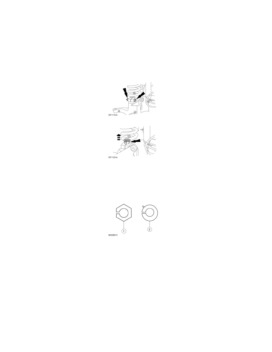
2. Remove the upper ball joint pinch bolt and nut.
-
Discard the nut.
3. Remove the existing adjuster sleeves. All vehicles are built by the assembly plant with a non-adjustable camber/caster sleeve.
1. Service adjusters have a 6-sided flange with the camber/caster adjustment range stamped into the top (0 degree, 1/4 degree, 1/2 degree, 3/4
degree or 1 degree, 1-1/4 degree and 1-1/2 degree).
2. Production adjusters have a round flange with a side tab. The amounts of pre-set camber and caster are stamped into the top of the adjuster.
4. Install interim 0 degree service adjusters to both sides of the vehicle.
5. Install the upper ball joint pinch bolt and a new nut.
-
Tighten to 80 Nm (59 lb-ft).
6. Install the front wheel(s) and check caster and camber readings with the 0 degree service adjusters installed.
7. Calculate the maximum amount of camber and/or caster adjustment required to achieve the optimal settings, as provided in the Alignment
Specifications table, by subtracting the measured values from the optimal target values.
Example: for an F-350 Rear Wheel Drive (RWD), DRW, Pickup,
-
optimal camber spec target = 0.62 ± 1.0.
-
optimal caster LH spec target = 4.0 ± 1.2.
-
measured camber = 1.85 (out-of-spec).
-
measured caster = 3.0 (within spec).