
F 250 2WD Super Duty V10-6.8L (2009)
GO to O3.
No
REPAIR the circuit. CONNECT the negative battery cable. CLEAR the DTCs. REPEAT the network test with the scan tool.
-------------------------------------------------
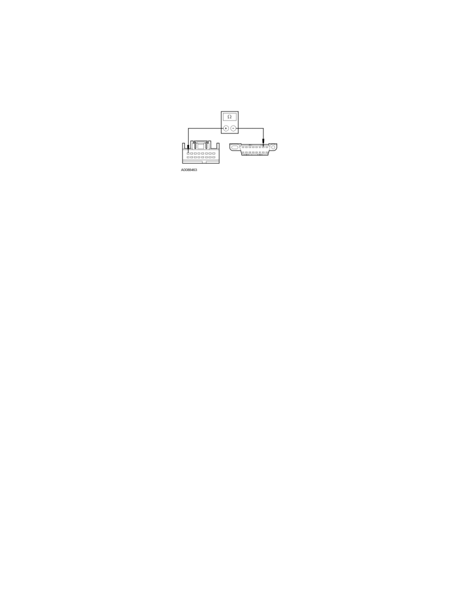
O3 CHECK THE ISO 9141 COMMUNICATION NETWORK CIRCUIT BETWEEN THE PAM AND THE DLC FOR AN OPEN
-
Measure the resistance between the PAM C2023-8, circuit VDB10 (GY), harness side and the DLC C251-7, circuit VDB10 (GY), harness side.
-
Is the resistance less than 5 ohms?
Yes
CONNECT the negative battery cable. GO to O4.
No
REPAIR the circuit. CONNECT the negative battery cable. CLEAR the DTCs. REPEAT the network test with the scan tool.
-------------------------------------------------
O4 CHECK FOR CORRECT PAM OPERATION
-
Disconnect the PAM connector.
-
Check for:
-
corrosion
-
damaged pins
-
pushed-out pins
-
Connect the PAM connector and make sure it seats correctly.
-
Operate the system and verify the concern is still present.
-
Is the concern still present?
Yes
INSTALL a new PAM. CLEAR the DTCs. REPEAT the network test with the scan tool.
No
The system is operating correctly at this time. The concern may have been caused by a loose or corroded connector. CLEAR the DTCs. REPEAT the
network test with the scan tool.
-------------------------------------------------
Pinpoint Test P: The 4X4 Control Module Does Not Respond To The Scan Tool
Communications Network
Pinpoint Tests
Pinpoint Test P: The 4X4 Control Module Does Not Respond To The Scan Tool
Refer to Wiring Diagram Set 14, Module Communications Network for schematic and connector information. See: Diagrams/Electrical
Diagrams/Diagrams By Number
Refer to Wiring Diagram Set 55, Automatic Climate Control System for schematic and connector information. See: Diagrams/Electrical
Diagrams/Diagrams By Number