
F 250 4WD LD Pickup V8-281 4.6L VIN W EFI (1997)
Flywheel: Component Tests and General Diagnostics
Clutch Surface
1. Use a fine grade sandpaper (400 grit) or if necessary, machine the flywheel surface to remove any defects. Make sure to not exceed the wear limit.
2. After machining the flywheel must meet specifications:
(1) Surface runout must not exceed 0.13 mm (0.005 in) TIR, surface finish must be in the range of 4.0/1.3 micrometer (160/52 microinch).
(2) The major diameter of any dowel pin must be below the new surface.
(3) The clutch pressure plate retaining bolts must screw into the flywheel by hand to within 1.50 mm (0.06 in) of the new surface.
Runout
1. Remove spark plugs.
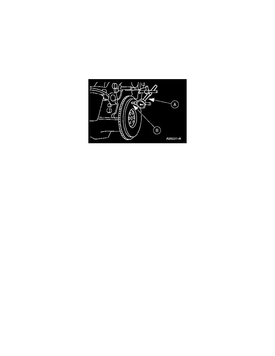
2. Install (A) Dial Indicator With Bracketry so indicator points rest on face of the flywheel (B).
3. Hold flywheel and crankshaft forward or backward as far as possible to prevent crankshaft end play from being indicated as flywheel runout.
4. Set indicator dial on zero mark. Turn flywheel one complete revolution while observing total indicator runout reading. If reading exceeds
specification, the flywheel must be replaced.
5. If clutch face runout exceeds specification, remove flywheel and check for burrs between flywheel and face of crankshaft mounting flange. If no
burrs exist, check runout of crankshaft mounting flange. Replace flywheel or machine crankshaft flywheel mounting face sufficiently to true-up the
surface