
F 250 4WD Super Duty V10-6.8L VIN V (2005)
Connecting Rod: Specifications
Connecting rod journal diameter ........................................................................................................................... 53.003-52.983 mm (2.0867-2.0859 in)
Connecting rod journal maximum taper .......................................................................................................................................... 0.004 mm (0.0002 in)
Connecting rod journal maximum out-of-round ....................................................................................... 0.0075 mm (0.0003 in) between cross sections
Connecting rod-to-pin clearance ............................................................................................................................. 0.009-0.0235 mm (0.0004-0.0093 in)
Connecting rod pin bore diameter ......................................................................................................................... 22.012-22.024 mm (0.8666-0.8671 in)
Connecting rod length (center-to-center) ......................................................................................................................................... 169.1 mm (6.6575 in)
Connecting rod maximum allowed bend ......................................................................................................................................... 0.038 mm (0.0015 in)
Connecting rod maximum allowed twist a ........................................................................................................................................ 0.05 mm (0.0020 in)
Connecting rod side clearance .................................................................................................................................. 0.475-0.125 mm (0.0187-0.0049 in)
a The pin bore and crank bearing bore must be parallel and in the same vertical plane within the specified total difference when measured at the ends
of a 203 mm bar, 105,5 mm on each side of rod centerline.
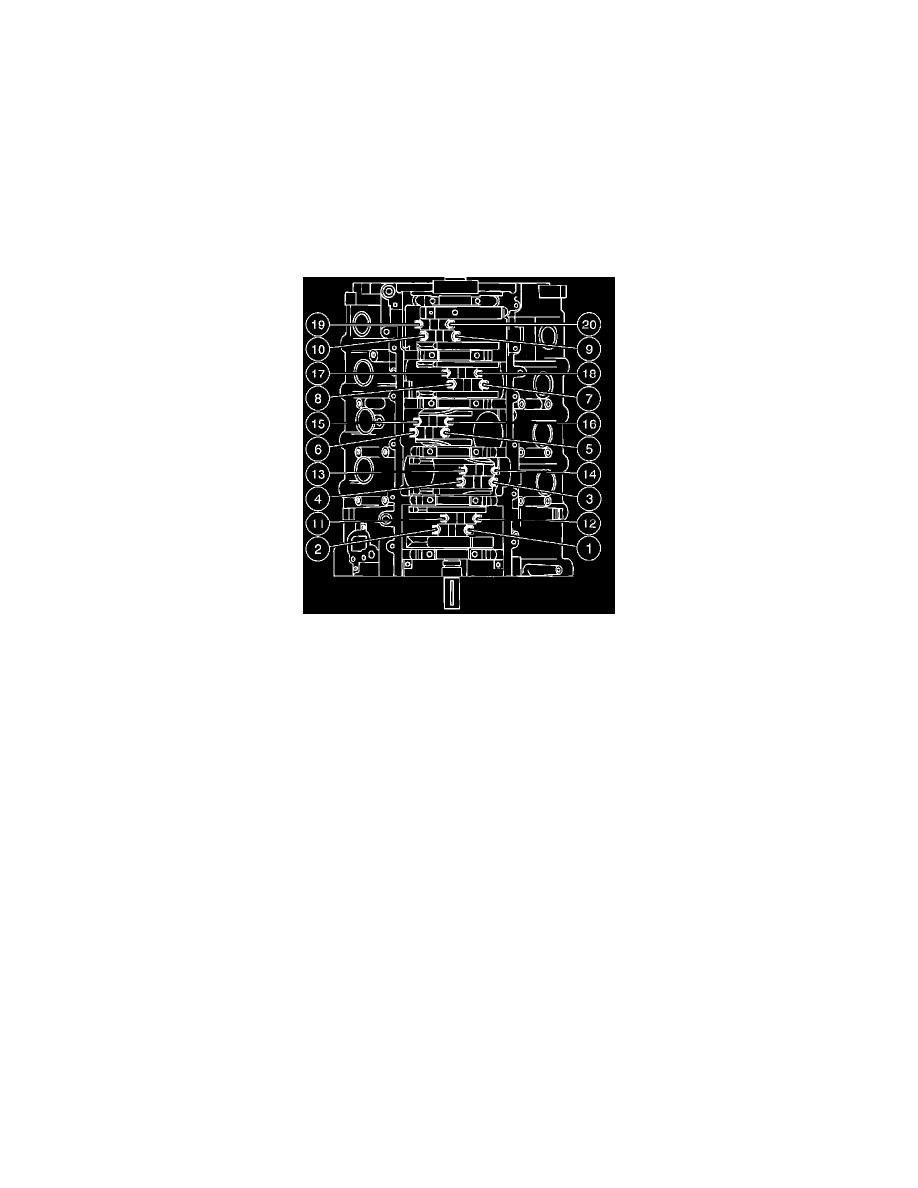
Connecting Rod
NOTE: Be sure to tighten the bolts in two stages.
Tighten the connecting rod bolts in the sequence shown.
Stage 1: Tighten to ......................................................................................................................................................................... 43 Nm (32 ft. lbs.).
Stage 2: Tighten an additional 105 degrees.