
F 250 4WD Super Duty V10-6.8L VIN Z CNG (2003)
position by the strategy.
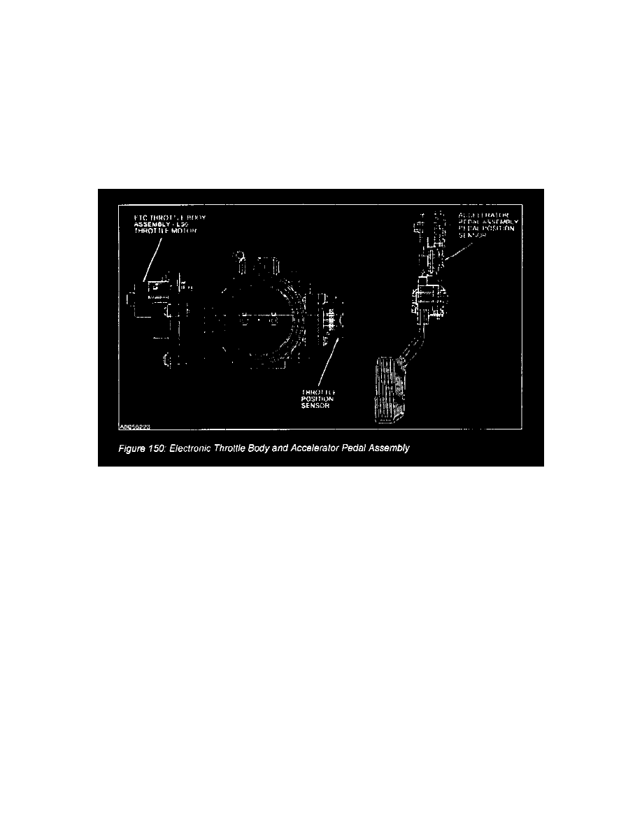
2. There are two VREF wires, two signal return wires and three signal wires (total of seven wires and pins) between the PCM and APPS assembly.
-
2- (5 V Reference Voltage)
-
2- (Signal Return "ground")
-
APP1 voltage with negative voltage slope (5-0)
-
APP2 voltage with positive voltage slope (0-5)
-
APP3 voltage with positive voltage slope (0-5)
3. The pedal position signal is converted to pedal travel degrees (rotary angle) by the PCM. The software then converts these degrees to counts,
which is the input to the torque based strategy.
4. The three pedal position signals ensure a correct input to the PCM, if any one signal has a fault. The PCM knows if a signal is wrong by
calculating where it should be, inferred by the other signals. A safe value will be substituted for a faulty signal if two out of the three signals are
bad.