
F 250 4WD Super Duty V10-6.8L VIN Z CNG (2003)
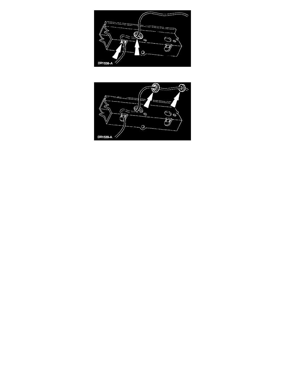
3. Route a sufficient length of copper welding wire through the weld nut clearance hole and back out an adjacent access hole.
4. Feed the copper welding wire through the weld nut, then through a standard flat washer.
5. Secure the flat washer so that it cannot be pulled off the end of the copper welding wire.
6. Pull the copper welding wire back through the clearance hole, allowing the weld nut and flat washer to follow the copper welding wire through.
7. Position the weld nut to the weld nut clearance hole, firmly pulling on the copper welding wire allowing the secured flat washer to hold the weld
nut in position.
8. Holding the weld nut securely in place and using a MIG welder, weld in four places around the edge of the weld nut.
9. Metal finish as required.
10. Verify the nut is securely in place.
11. Install the crash sensor.
12. Tighten the attaching screws to specification. Refer to Torque Specifications.
Stripped Weld Nut, Restraints Control Module (Rcm)
WARNING: TO AVOID ACCIDENTAL DEPLOYMENT AND POSSIBLE PERSONAL INJURY, THE BACKUP POWER SUPPLY MUST
BE DEPLETED BEFORE REPAIRING OR REPLACING ANY FRONT OR SIDE AIR BAG SUPPLEMENTAL RESTRAINT SYSTEM
(SRS) COMPONENTS AND BEFORE SERVICING, REPLACING, ADJUSTING OR STRIKING COMPONENTS NEAR THE FRONT OR
SIDE AIR BAG SENSORS, SUCH AS DOORS, INSTRUMENT PANEL, CONSOLE, DOOR LATCHES, STRIKERS, SEATS AND HOOD
LATCHES.
PLEASE REFER TO THE APPROPRIATE COMPONENT OR SYSTEM TO DETERMINE LOCATION OF THE FRONT AIR BAG
SENSORS.
THE SIDE AIR BAG SENSORS ARE LOCATED AT OR NEAR THE BASE OF THE B-PILLAR.
TO DEPLETE THE BACKUP POWER SUPPLY ENERGY, DISCONNECT THE BATTERY GROUND CABLE AND WAIT AT LEAST
ONE MINUTE. BE SURE TO DISCONNECT AUXILIARY BATTERIES AND POWER SUPPLIES (IF EQUIPPED).
1. Obtain an 8 mm (0.32 in) grounding screw (part number N802455-S190).
2. Drill out the internal threads of the stripped-out weld nut to 7.37 mm (0.29 in) using a letter "L" size drill bit.
3. Position the crash sensor to the vehicle.
4. Install the 8 mm (0.32 in) grounding screw into the drilled-out weld nut.
5. Install the remaining attaching screws.
6. Tighten the attaching screws to specification. Refer to Torque Specifications.